
Porous body, production method thereof and composite material using the porous body

a technology of porous body and fiber, which is applied in the direction of catalyst activation/preparation, synthetic resin layered products, and final product manufacturing. it can solve the problems of insufficient degree of three-dimensional network formation between fiber filaments, difficult design, and difficult preparation of prepregs of vapor grown carbon fiber. , to achieve the effect of low volumetric shrinkage, easy to manufacture and use, and easy to design

Inactive Publication Date: 2007-02-22
SHOWA DENKO KK
View PDF18 Cites 17 Cited by
  • Summary
  • Abstract
  • Description
  • Claims
  • Application Information

AI Technical Summary

Benefits of technology

[0015] Another object of the present invention is to provide a method for readily producing a composite material (porous material) containing vapor grown carbon fiber and a resin and the like, wherein the vapor grown carbon fiber exhibits its effects even when added in a small amount.
[0056] Reduction of the electrical resistivity (i.e., enhancement of the electrical conductivity) of the porous material can be attained by, for example, increasing the amount of the vapor grown carbon fiber incorporated into the porous material, thermally treating the porous material after removal of the solvent, or enhancing the electrical conductivity of the vapor grown carbon fiber. In the porous material of the present invention, fiber filaments of the carbon fiber are highly connected to one another, forming a high-level three-dimensional network. Therefore, even when the amount of the vapor grown carbon fiber is not increased to the level in the case of the conventional porous material, the electrical resistivity can be reduced to a target level. Composite Material

Problems solved by technology

Meanwhile, preparation of a prepreg of vapor grown carbon fiber is very difficult as compared with the case of a prepreg of the carbon fiber described in the aforementioned patent documents, since, for example, vapor grown carbon fiber has a diameter smaller than that of the aforementioned carbon fiber.
Even when a prepreg can be formed from vapor grown carbon fiber, the prepreg contains only small amounts of pores, and therefore, the prepreg fails to be sufficiently impregnated with a material for preparing a composite material.
However, in the method, during the course of kneading, fiber filaments of the carbon fiber are cut into short fiber fragments, and thus the degree of three-dimensional network formation between the fiber filaments becomes insufficient.
However, addition of a large amount of vapor grown carbon fiber causes problems, including deterioration of flow characteristics of the resin during the course of molding, and an increase in production cost.
However, the production methods disclosed in the aforementioned publications involve problems attributed to the following: vapor grown carbon fiber is contained in the form of aggregates in the porous material, an operation for applying high shear force is performed in order to separate the aggregates into individual fiber filaments, and excessive kneading is performed by use of a kneading machine during the production of the porous material.
Therefore, the amount of the vapor grown carbon fiber to be added must be increased, which may lead to lowering of moldability and the like.
Thus the degree of three-dimensional network formation between the fiber filaments becomes insufficient, which causes the problems similar to those aforementioned when the amount of the vapor grown carbon fiber to be added must be increased.
However, this method involves a problem that the molded member considerably shrinks in volume during the course of thermal treatment.

Method used


Image

  • Porous body, production method thereof and composite material using the porous body
  • Porous body, production method thereof and composite material using the porous body
  • Porous body, production method thereof and composite material using the porous body

Examples


example 1

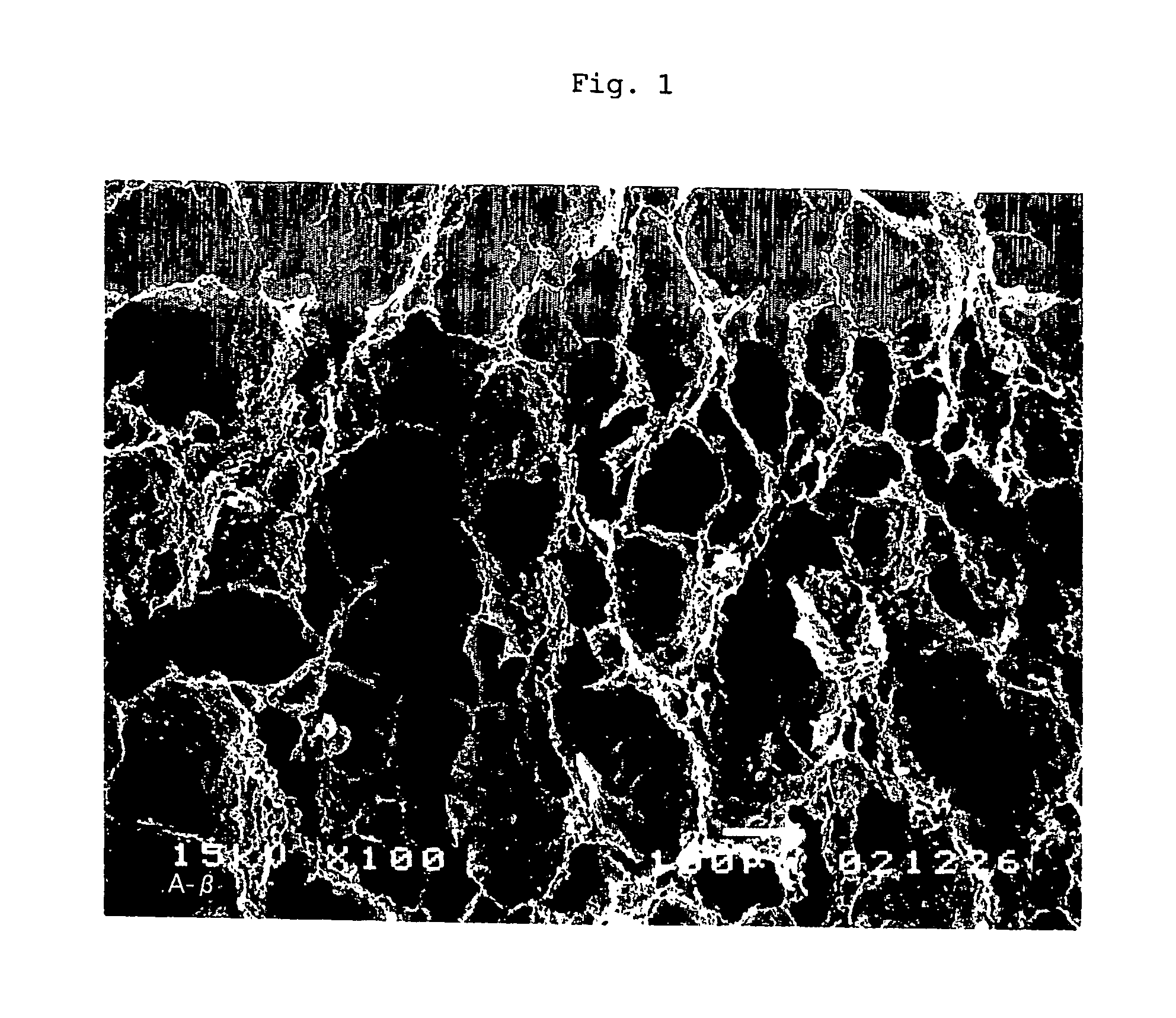
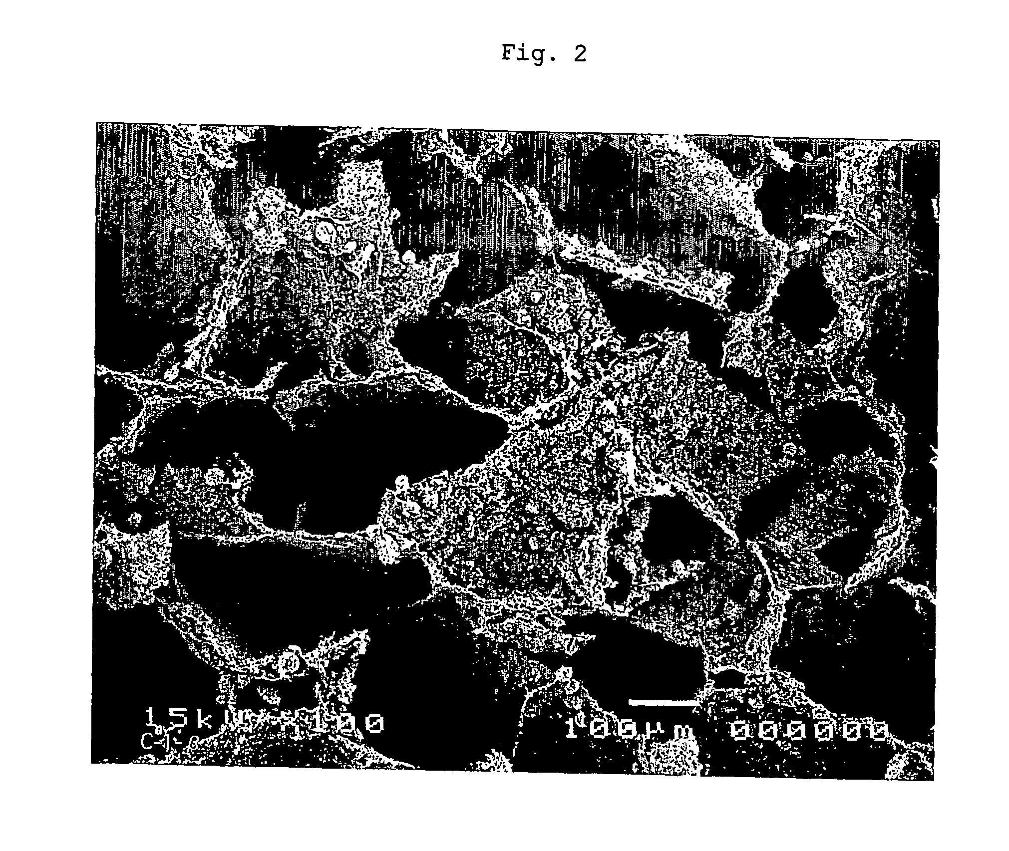
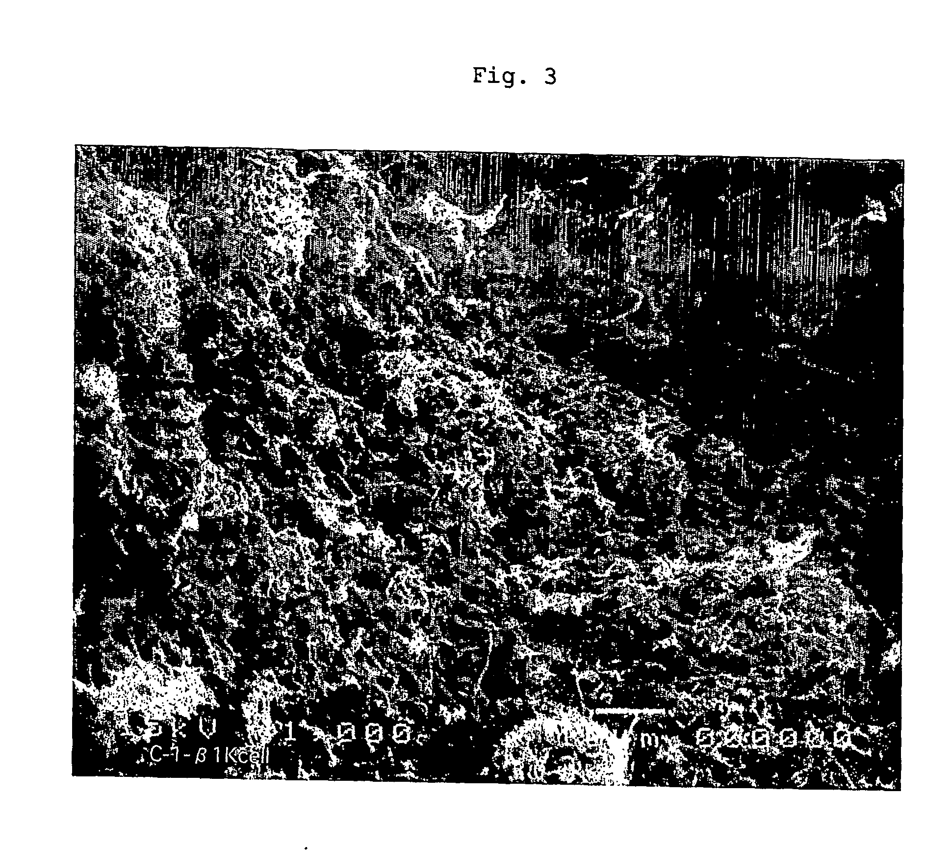
[0070] Agar (1.5 g) was dissolved in purified water (50 g) under heating at 95° C., to thereby prepare a solution (the solution will be called “liquid A”). Separately, sodium dodecylbenzenesulfonate (concentration: 40 mass %, product of Aldrich) (0.45 g) was added to purified water (75 g). To the resultant mixture was added vapor grown carbon fiber (VGCF (registered trademark), product of Showa Denko K.K.; fiber diameter: 150 nm, aspect ratio: 60, specific surface area: 13 m2 / g, Raman spectrum intensity ratio: 0.15) (4.2 g). The resultant mixture was subjected to ultrasonic irradiation for 30 minutes, and then to stirring for one hour by use of a magnetic stirrer, to thereby prepare a dispersion (the dispersion will be called “liquid B”).

[0071] After being cooled to 60° C., the liquid A was mixed with the liquid B. Thereafter, the resultant mixture was frozen in a freezer at -15° C. to −20° C. Subsequently, the thus-frozen product was removed from the freezer, and placed in a freez...

example 2

[0073] The porous material produced in Example 1 was thermally treated in a tubular heating furnace under a stream of argon gas (10 L / min) at 800° C. for one hour. The thus-treated porous material was found to have a porosity of 0.98, a vapor grown carbon fiber content of 93 mass %, a specific surface area of 520 m2 / g, and a volume resistivity of 40 Ω·cm. The percent volumetric shrinkage of the porous material during thermal treatment was found to be 13 vol.%.

example 3

[0074] Agar (1.5 g) was dissolved in purified water (50 g) under heating at 95° C., to thereby prepare a solution (the solution will be called “liquid A”). Separately, sodium dodecylbenzenesulfonate (concentration: 40 mass %, product of Aldrich) (0.45 g) was added to purified water (75 g). To the resultant mixture was added vapor grown carbon fiber (VGCF (registered trademark), product of Showa Denko K.K.; fiber diameter: 150 nm, aspect ratio: 60, specific surface area: 13 m2 / g, Raman spectrum intensity ratio: 0.15) (8.5 g). The resultant mixture was subjected to ultrasonic irradiation for 30 minutes, and then to stirring for one hour by use of a magnetic stirrer, to thereby prepare a dispersion (the dispersion will be called “liquid B”).

[0075] After being cooled to 60° C., the liquid A was mixed with the liquid B. Thereafter, the resultant mixture was frozen in a freezer at -15° C. to −20° C. Subsequently, the thus-frozen product was removed from the freezer, and subjected to free...


PUM

PropertyMeasurementUnit
Temperatureaaaaaaaaaa
Percent by massaaaaaaaaaa

Abstract

A porous material comprising vapor grown carbon fiber in an amount of 10 to 90 mass %, fiber filaments of the carbon fiber forming a three-dimensional network and having a diameter of 1 to 1,000 nm, an aspect ratio of 5 to 15,000, a specific surface area (by BET method) of 2 to 2,000 m2 / g, and the ratio of the intensity of the peak at 1,360 cm−1 in a Raman scattering spectrum of the carbon fiber to that of the peak at 1,580 cm−1 in the spectrum(I1360 / I1580) is 0.1 to 2.0, wherein the porosity of the porous material (V / V0) is 0.50 to 0.99 and a specific surface area is 5 to 1,000 m2 / g; and a production method and use thereof. The vapor grow carbon fiber impregnated in the porous material of the present invention does not contain aggregates and a three-dimensional network is formed between the fiber filaments, wherein length of each of the fiber filaments is maintained. Therefore, the vapor grown carbon fiber enables to readily produce a composite material (porous material), in which even a small amount of addition of vapor grown carbon fiber can exhibit sufficient effect.

Description

CROSS REFERENCE TO THE RELATED APPLICATIONS [0001] This is an application filed pursuant to 35 U.S.C. Section 111(a) with claiming the benefit of U.S. Provisional application Ser. No. 60 / 472,129 filed May 21, 2003 under the provision of 35 U.S.C. Section 111(b), pursuant to 35 U.S.C. Section 119(e)(1).TECHNICAL FIELD [0002] The present invention relates to a porous material containing vapor grown carbon fiber. More particularly, the present invention relates to a porous composite material containing vapor grown carbon fiber and a gelable substance, which material is obtained by dispersing vapor grown carbon fiber in a solution of an organic or inorganic gelable substance (i.e., a raw material capable of being gelled), and gelling the gelable substance, followed by removing the solvent and drying; to a method for producing the composite material; and to use of the same. BACKGROUND ART [0003] Carbon fiber produced through melt-spinning of petroleum pitch or polyacrylonitrile, or vapor...

Claims


Application Information

Patent Timeline
IPC IPC(8): B01J21/18B01J31/06B01J32/00C04B38/00C04B41/48C04B41/51C04B41/83C04B41/88C08J9/00C08J9/26C08J9/40C08K7/06C22C47/08
CPCB01J21/18B01J31/06B01J31/08B01J35/0033B01J35/10B01J37/32C02F1/283C02F2303/185C04B38/0045C04B41/009C04B41/4888C04B41/51C04B41/63C04B41/69C08J9/0085C08J9/28C08J9/40C08J2201/038C08J2201/0504C08J2305/00C08J2375/04H01M4/9083H01M4/926H01M8/0234C04B35/52C04B38/04C04B40/0078C04B14/386C04B30/02C04B38/00Y10S977/842Y10T428/249927Y10T428/24994B01J35/1014B01J35/002B01J35/023B01J35/026B01J35/06Y10T428/30Y02P70/56B01J31/061B22F2998/10C04B41/48C04B41/83C04B41/88C04B2111/00793C04B2111/0081C08J9/26C08J2201/048C22C47/08Y02P70/50Y02E60/50B01J35/50B01J35/30B01J35/33B01J35/58B01J35/60B01J35/40B01J35/613C04B38/0074C04B38/10C04B41/457C04B41/4523C04B35/83C22C47/06B22F3/114
Inventor KUROSE, TAKASHITAKAHASHI, TATSUHIROSOTOWA, CHIAKIMORITA, TOSHIO
Owner SHOWA DENKO KK
Learn More