Pattern formed body and method for manufacturing same

a technology of forming body and forming plate, which is applied in the direction of photosensitive materials, printers, instruments, etc., can solve the problems of difficult printing process use, waste liquid treatment, and low location accuracy, and achieve the effect of good adhesion property between the functional part and the base material

Inactive Publication Date: 2007-02-22
DAI NIPPON PRINTING CO LTD
View PDF9 Cites 0 Cited by
  • Summary
  • Abstract
  • Description
  • Claims
  • Application Information

AI Technical Summary

Benefits of technology

[0013] This makes it possible that a difference in wettability between the upper face of the liquid repellent resin layer and the region where the intermediate layer is exposed is made large, thereby manufacturing a pattern formed body capable of forming a functional part further highly precisely.
[0014] The present invention also provides: a color filter, wherein a colored layer is formed on the lyophilic region of the above-mentioned pattern formed body; an organic EL element, wherein an organic EL layer is formed on the lyophilic region of the above-mentioned pattern formed body; and a microlens, wherein a lens is formed on the lyophilic region of the above-mentioned pattern formed body. According to the invention, in the pattern formed body, the region where the liquid repellent resin layer is formed, that is, the liquid repellent region, and the lyophilic region are formed; therefore, the wettability difference therebetween is used to make it possible to manufacture a functional element wherein various functional parts are highly precisely formed only in the lyophilic region. The invention also has an advantage that in this case the adhesive property between the functional part and the base material can be made good.
[0015] The invention also provides a cell culturing substrate, wherein the upper face of the lyophilic region of the above-mentioned pattern formed body is used to culture a cell. According to the invention, in the pattern formed body, the liquid repellent region and the lyophilic region are formed; therefore, the wettability difference therebetween is used to make it possible to manufacture a cell culturing substrate for culturing cells in a highly precise pattern only in the lyophilic region.
[0016] In the method for manufacturing the pattern formed body of the invention, the wettability difference between the resin layer and the region where the intermediate layer is exposed can be made large since the above-mentioned plasma radiating step is performed. Accordingly, this wettability difference is used to make it possible to manufacture a pattern formed body capable of forming a functional part highly precisely only in the region where the intermediate layer is exposed. Additionally, the invention produces advantages that: as the base material, various ones can be used; and further the adhesive property between the base material and the functional part can be made good.

Problems solved by technology

However, the above-mentioned printing processes have a problem such as that at the time of manufacturing a highly precise pattern formed body used in, for example, a color filter, only a low location accuracy is attained.
Thus, it is difficult to use the printing processes.
The above-mentioned photolithography has a problem that it becomes necessary to treat waste liquid since it is necessary to use a photoresist and further develop the resist with a developing solution or perform etching after radiation of light to the resist, and other problems.
When a functional material is used as a photoresist to form a functional part, there is caused a problem that the functional part is deteriorated by such as an alkaline solution that is used in development.
However, in this method, as the base material, one made of an organic material cannot be used and one made of an inorganic material is used; therefore, there is caused a problem that the adhesive property between the bank or the functional part of a colored layer formed by using the bank and the base material becomes low.
Additionally, for example, even if a base material made of an organic material is used, there arise a problem by the above-mentioned plasma radiation that the adhesive property between the base material and the bank of the resin layer declines, and other problems.

Method used


Image

  • Pattern formed body and method for manufacturing same
  • Pattern formed body and method for manufacturing same

Examples


examples

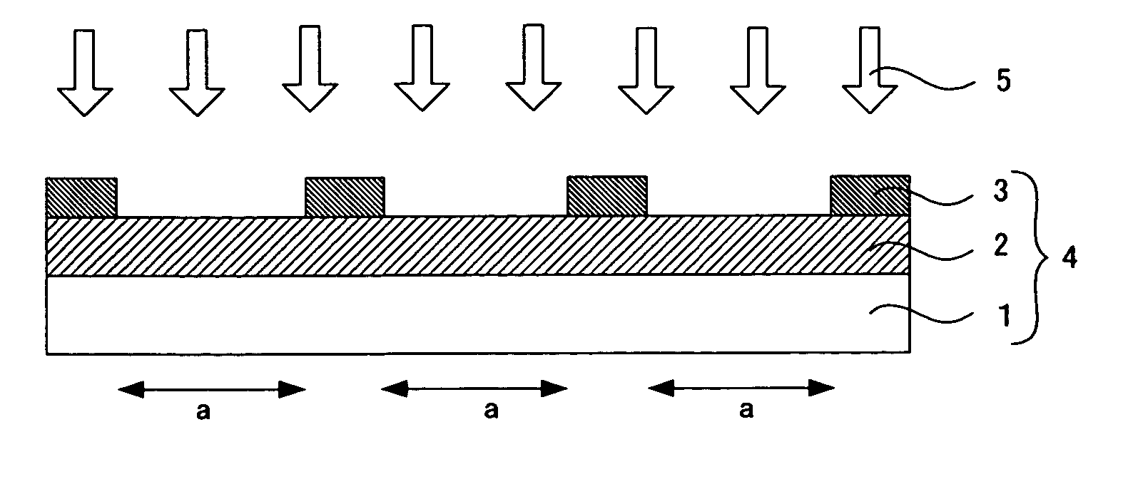
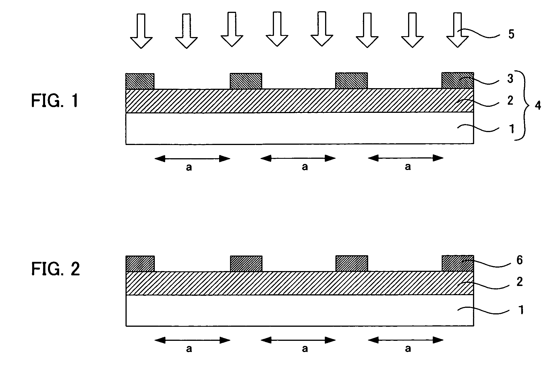
[0082] Mixed and stirred for 5 hours were 1.5 g of decyltrimethoxysilane, 5 g of tetramethoxysilane, and 2 g of 0.1 N hydrochloric acid. The resultant was diluted 10 times with isopropanol, and then the solution was uniformly coated onto a 370 mm×470 mm×0.7 mm glass substrate with a spin coater, so as to yield an intermediate layer having a film thickness of 0.1 μm.

[0083] A black resist containing carbon black (V-259 BK resist, manufactured by Nippon Steel Chemical Co., Ltd.) was coated onto the glass substrate, and the resultant was exposed to light, developed and subjected to post-baking treatment to form a resin layer with a light shielding property having a film thickness of 1.0 μm, a width of 20 μm, and an opening part of 280 μm squares.

[0084] CF4 and N2 were caused to flow onto the substrate at 10 L / min, and 20 L / min, respectively. This treatment was conducted twice at a transporting rate of 0.5 m / min, so as to manufacture a pattern formed body. At this time, the power outpu...


PUM

PropertyMeasurementUnit
contact angleaaaaaaaaaa
distanceaaaaaaaaaa
distanceaaaaaaaaaa

Abstract

A main object of the present invention is to provide a pattern formed body capable of forming highly precise functional parts on various base materials, and a method for manufacturing the same. To achieve the object, the present invention provides a method for manufacturing a pattern formed body, having a plasma radiating step of radiating plasma to a patterning substrate having: a base material; an intermediate layer formed on the base material and containing a silane coupling agent or a polymer of the silane coupling agent; and a resin layer formed in a pattern form on the intermediate layer, wherein a fluorine gas is used as an introduction gas to radiate the plasma from the resin layer side.

Description

BACKGROUND OF THE INVENTION [0001] 1. Field of the Invention [0002] The present invention relates to a pattern formed body which is capable of forming a highly precise functional part and is used to manufacture such as a color filter, a microlens, an organic electroluminescent (hereinafter, may be referred to as an organic EL) element, or a cell culturing substrate; a method for manufacturing the same; and so on. [0003] 2. Description of the Related Art [0004] Conventionally, various methods have been suggested as a method for manufacturing a pattern formed body wherein various patterns such as designs, images, characters, and circuits are formed on a base material. For example, the following is used: lithography, offset printing, or a printing process wherein a lithographic original plate using a heat mode recording material is formed. There is also known, for example, a method for manufacturing a pattern formed body by photolithography of radiating light in a pattern form to a pho...

Claims


Application Information

Patent Timeline
Patent Type & Authority Applications(United States)
IPC IPC(8): G03B27/52
CPCC12N5/0068C12N2533/30Y10T428/24802
Inventor KOBAYASHI, HIRONORI
Owner DAI NIPPON PRINTING CO LTD
Why Eureka
Try Eureka