
Method of regenerating stator vane of gas turbine and gas turbine

a technology of stator vane and gas turbine, which is applied in the direction of turbines, manufacturing tools, and so on, can solve the problems of gas turbine stator vane suffering various damages, cracks that are liable to be unavoidably caused, creep cracking, corrosion, etc., and achieves small deformation

Inactive Publication Date: 2007-02-22
KK TOSHIBA
View PDF11 Cites 25 Cited by
  • Summary
  • Abstract
  • Description
  • Claims
  • Application Information

AI Technical Summary

Benefits of technology

The present invention provides a method for regenerating a gas-turbine stator vane with deteriorated or damaged portions without requiring complete grinding and deformation correction. The method involves heat treatment using a diffusion-brazing method, followed by brazing treatment to seal the repaired portion. The method reduces the amount of material to be ground, saves man-power, and improves the strength of the repaired portion. The invention also provides a gas-turbine stator vane regenerated using this method.

Problems solved by technology

Therefore, many cracks are liable to be unavoidably caused to the stator vane.
Further, the gas-turbine stator vane suffers various damages such as creep cracking, fatigue cracking, thermal deterioration, oxidation, corrosion, erosion caused by being exposed to a high temperature atmosphere, or FOD caused by the collision with flying objects.
In this situation, heat affection by the welding operation during the repairing work becomes remarkable and residual stress in the stator vane is greatly increased, so that it becomes difficult to eliminate the heat affection and remove the residual stress.
Moreover, an amount of deformation is also largely increased, and the deformation amount cannot be easily corrected through a standard deformation-correcting work to be performed after the repairing work.
However, since the cracks caused by the thermal stress or the thermal fatigue resulting from the start and stop operations of the gas turbine are unavoidably generated in a large number, when the conventional repairing method in which the cracked portion is entirely ground and then the ground portion is repair-welded by TIG method is adopted, a repairing amount necessary for the welding is greatly increased.
In addition, the heat affection by the welding operation during the repairing work becomes remarkable and residual stress is greatly increased, so that it becomes difficult to eliminate the heat affection and remove the residual stress.
Moreover, an amount of deformation is also largely increased, and the deformation amount cannot be easily corrected through a standard deformation-correcting work to be performed after the repairing work.
Namely, segregation of the melting point lowering agent is liable to occur, and the mixed material and the base material are bonded without completely melting the base material, so that there cannot be obtained a sufficient bonding strength at a boundary surface between the two materials.
As a result, there cannot be obtained a fatigue strength or ductility corresponding to those of the base material.
Further, even in any of other conventional techniques, the oxidized films formed on the cracks caused during the operation of the gas turbine cannot be easily removed.
Accordingly, it requires much labor for grinding or gouging the cracked portion, thus resulting in high-cost situation.

Method used


Image

  • Method of regenerating stator vane of gas turbine and gas turbine
  • Method of regenerating stator vane of gas turbine and gas turbine
  • Method of regenerating stator vane of gas turbine and gas turbine

Examples


Embodiment Construction

[0043] Referring to the accompanying drawings, an embodiment of the present invention will be now explained.

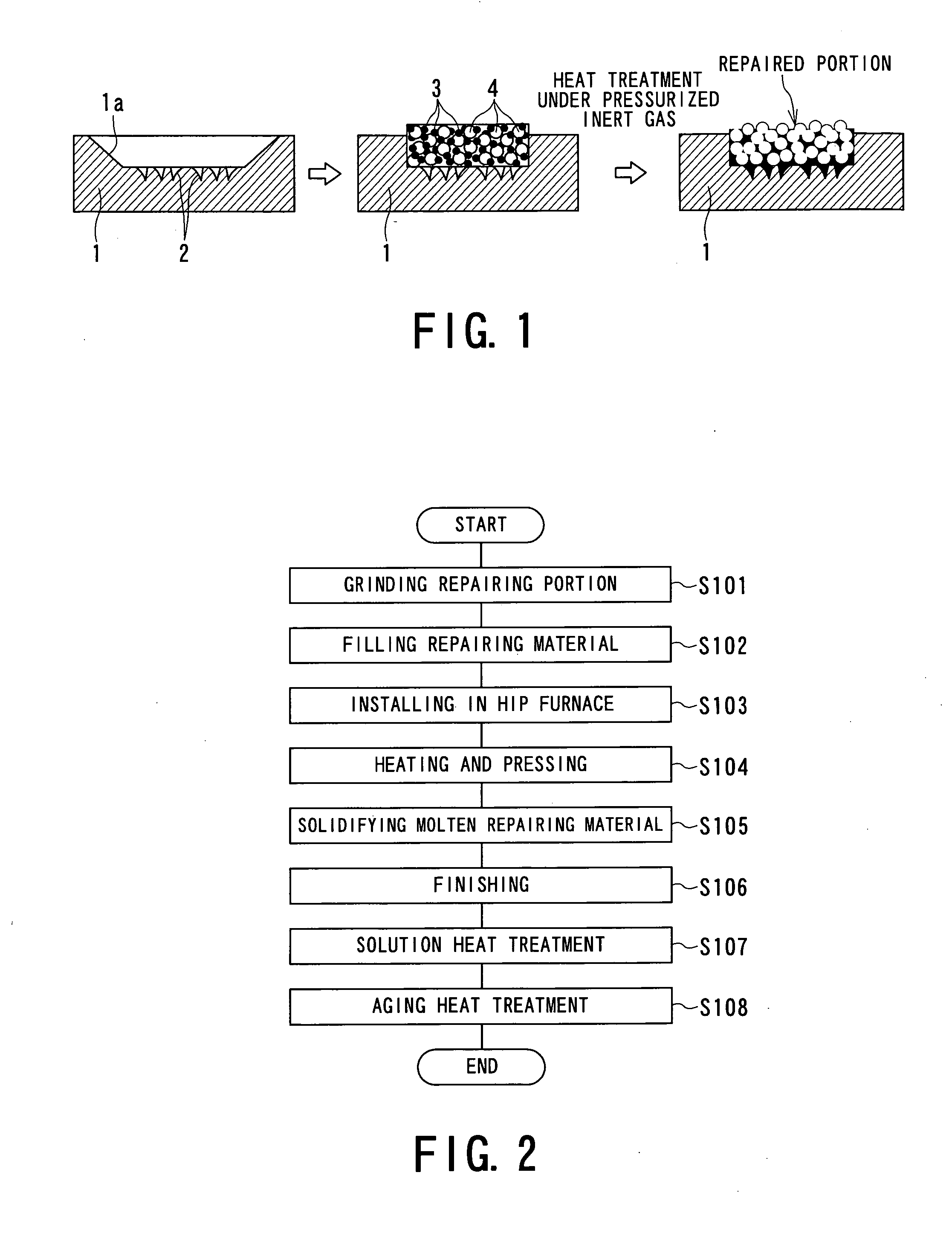
[0044]FIG. 1 is an explanatory view showing a process of regenerating a gas turbine stator vane, as one embodiment of the present invention, and FIG. 2 is a flowchart showing a procedure for the regenerating treatment.

[0045] As shown in FIGS. 1 and 2, in the embodiment of the present invention, a repairing portion of a base material 1 composed of Ni-based alloy in the gas turbine stator vane is ground by means of grinder or the like (S101). In this case, an oxidized layer formed at surface portion of the gas turbine stator vane at which cracks 2 are generated is ground so that a part of the cracks 2 remains. That is, although the oxidized layer formed at surface portion of the gas turbine stator vane is ground, the cracks are not completely ground but ground so as to remain a part of the cracks in a ground portion 1a.

[0046] Namely, with respect to the closed cracks, a surfa...


PUM

PropertyMeasurementUnit
pressureaaaaaaaaaa
temperatureaaaaaaaaaa

Abstract

A method of regenerating gas-turbine stator vane comprising the steps of: grinding the oxidized layer and the cracks 2 formed at surface portion so that a part of the cracks 2 remains; filling an equivalent material and a brazing material 4 into the ground portion, the equivalent material 3 having an equality with the base material 1 for the stator vane, and the brazing material 4 having a melting point lower than that of the equivalent material 3; heat treating the filled portion under pressurized inert gas atmosphere so as to melt the brazing material; performing brazing treatment by diffusing the molten brazing material into the cracked portions. According to the above method, the stator vane occurred with material deterioration and damages or the like due to operation of a gas turbine can be efficiently regenerated to provide a high quality without requiring to completely grinding and removing the cracks including a closed crack formed at surface of the stator vane.

Description

BACKGROUND OF THE INVENTION [0001] 1. Field of the Invention [0002] The present invention relates to a method of regenerating gas-turbine stator vane (nozzle) of which constituting material had been deteriorated or damaged, particularly to a method of regenerating gas-turbine stator vane suffered various damages such as thermal fatigue damage, creep damage, fatigue failure caused by start and stop operation of the gas turbine, thermal deterioration, oxidation, corrosion, erosion caused by being exposed to a high temperature atmosphere, or foreign object damage (FOD) caused by collision with flying objects. The present invention also relates to a gas-turbine stator vane which is regenerated by conducting this regenerating method, and to a gas turbine provided with the regenerated stator vane. [0003] 2. Description of the Related Art [0004] High temperature parts constituting a gas turbine, particularly a stator vane provided at a first stage corresponding to an inlet of combustion ga...

Claims


Application Information

Patent Timeline
Patent Type & Authority Applications(United States)
IPC IPC(8): B23P6/00B23P19/04
CPCB23K1/0018B23K20/021B23K2201/001Y10T29/49318Y10T29/49732Y10T29/49737B23P6/007B23K2101/001
Inventor YOSHIOKA, YOMEIFUSE, TOSHIAKINAKAHASHI, MASAKOSAITO, DAIZOOKAMOTO, HIROAKIISHIBASHI, KAZUTOSHI
Owner KK TOSHIBA
Learn More