
Separator and cell using the same for use in solid polymer electrolyte fuel cell

a solid polymer electrolyte and separator technology, applied in the field of solid polymer electrolyte fuel cells, can solve the problems of reducing performance and reliability, affecting the overall size affecting the efficiency of the fuel cell, so as to achieve the effect of ensuring sufficient reinforcing rib projection length, high rigidity and electrical performance, and compact cell structur

Inactive Publication Date: 2007-02-08
SUMITOMO RIKO CO LTD
View PDF15 Cites 11 Cited by
  • Summary
  • Abstract
  • Description
  • Claims
  • Application Information

AI Technical Summary

Benefits of technology

[0013] It is therefore one object of the present invention to provide a separator for a solid polymer electrolyte fuel cell of novel construction, whereby the separator can be made thinner while ensuring component rigidity to consistently ensure sealing in the gas flow zone, whereby a more compact fuel cell may be advantageously achieved.

Problems solved by technology

However, there it the problem that when large numbers of cells are stacked, the overall size of the fuel cell becomes rather large.
However, where the first and second separators are made thinner, rigidity of the components is lower, and thus during transport subsequent to manufacture or during assembly, there is a risk that the separators may become deformed.
If a separator becomes deformed, in the assembled cell there is an attendant risk of diminished sealing of the gas flow zone formed between the juxtaposed faces of the membrane / electrode assembly and the separator, creating the possibility of diminished performance and reliability.
Accordingly, it was very difficult to design a more compact fuel cell by means of reducing separator thickness.

Method used


Image

  • Separator and cell using the same for use in solid polymer electrolyte fuel cell
  • Separator and cell using the same for use in solid polymer electrolyte fuel cell
  • Separator and cell using the same for use in solid polymer electrolyte fuel cell

Examples


Embodiment Construction

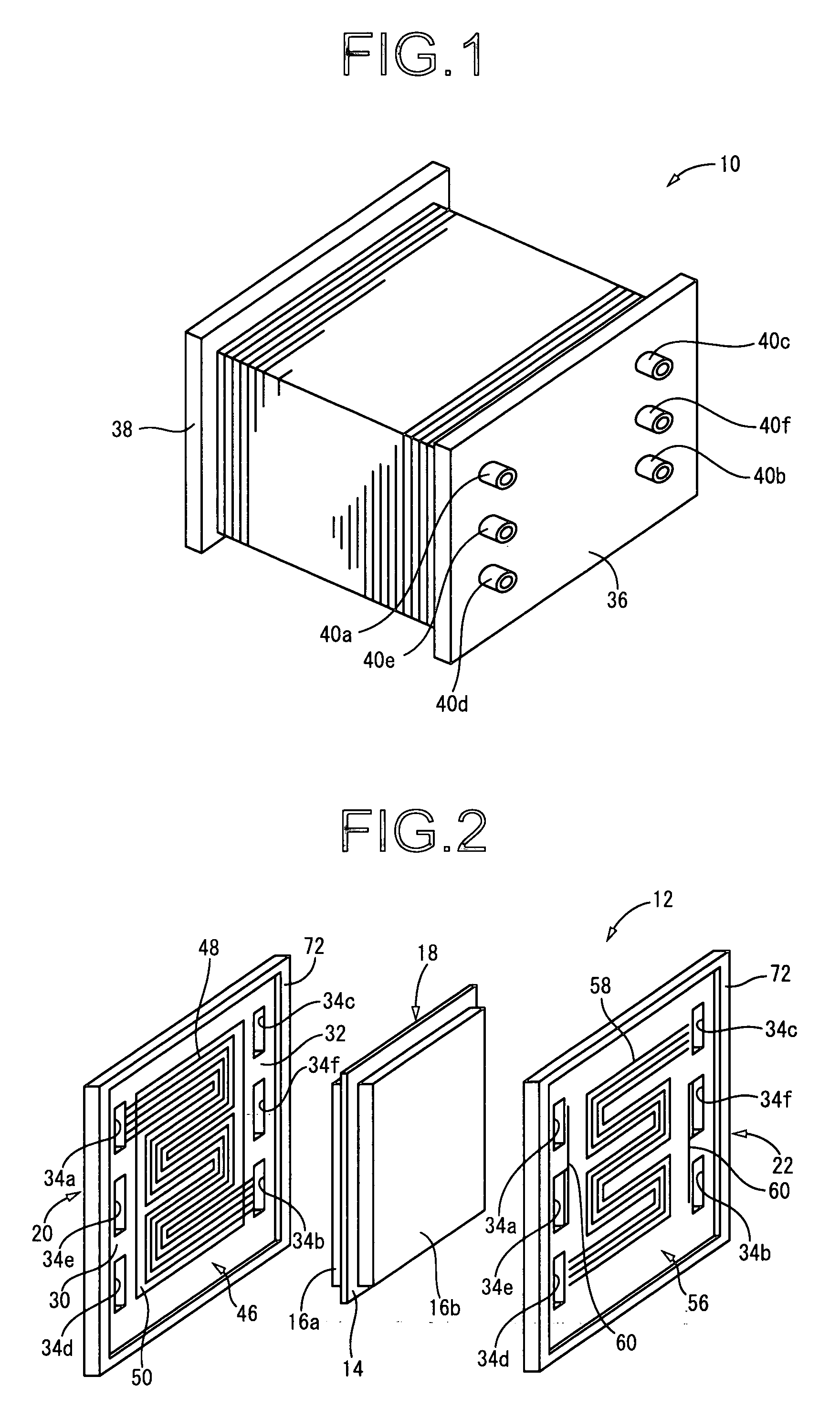
[0057] A simplified perspective view of a solid polymer electrolyte fuel cell (PEFC) 10 composed of a stack of multiple unit cells 12 constructed according to the invention is depicted in FIG. 1. The solid polymer electrolyte fuel cell 10 depicted in FIG. 1 is arranged with the vertical and sideways directions in the illustrated state aligned with the plumb-bob vertical and horizontal directions. In the description hereinabove, as a general rule, the vertical and sideways directions, and plumb-bob vertical and horizontal directions, refer to those in the state illustration in FIG. 1.

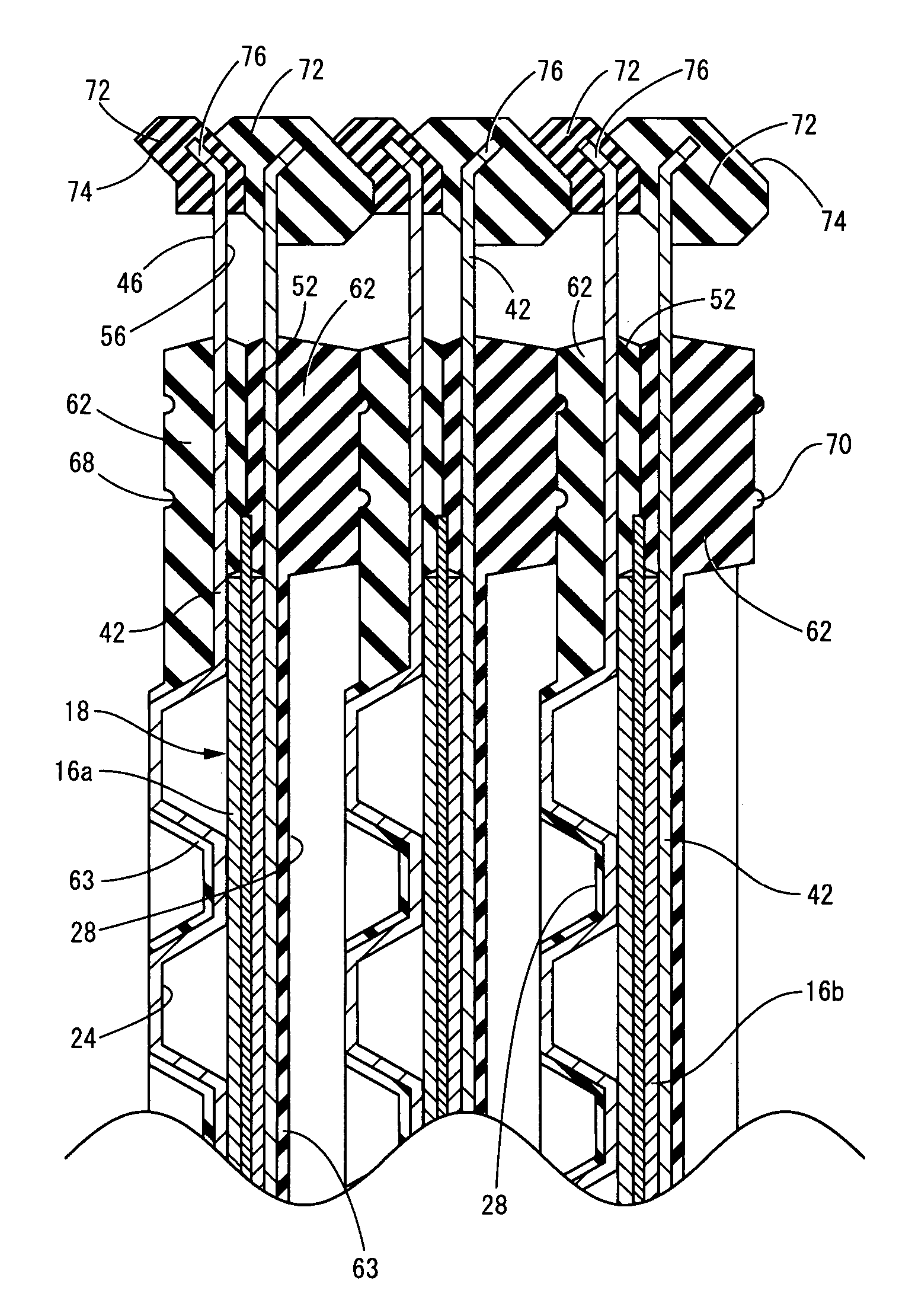
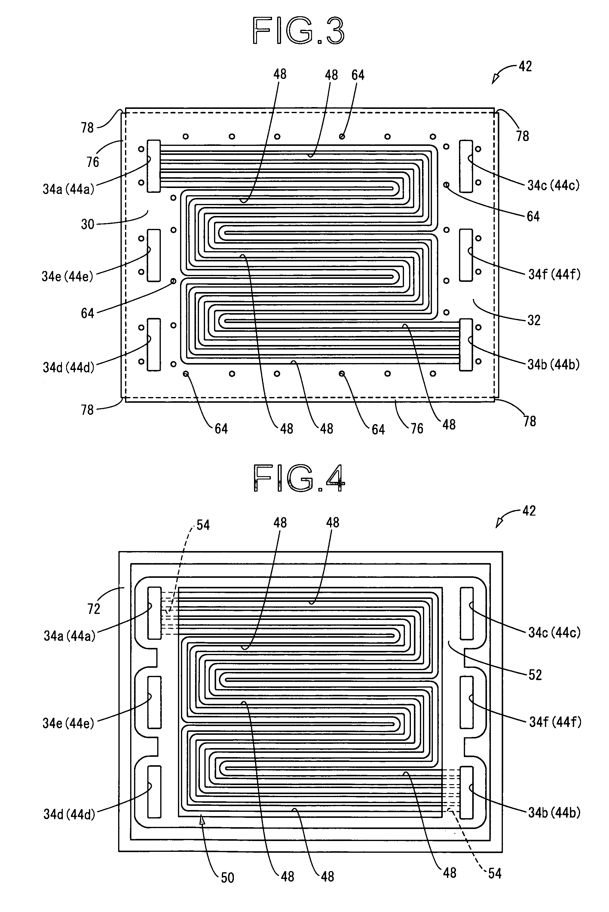
[0058] More specifically, as shown in FIG. 2, the unit cells 12 making up the solid polymer electrolyte fuel cell 10 comprise a membrane / electrode assembly (MEA) 18 having as the electrolyte a solid polymer membrane 14 as a solid polymer electrolyte membrane such as a solid ion exchange membrane with a fuel electrode 16a and an oxidant electrode 16b as a pair of catalyst electrodes superposed to either ...


PUM

PropertyMeasurementUnit
thicknessaaaaaaaaaa
depthaaaaaaaaaa
depthaaaaaaaaaa

Abstract

A separator for use in a solid polymer electrolyte fuel cell, including a membrane / electrode assembly including a fuel electrode and an oxidant electrode disposed on either side of a solid polymer electrolyte membrane; a first separator superposed against a surface of the oxidant electrode forming an oxidant gas flow passage; and a second separator superposed against a surface of the fuel electrode forming a fuel gas flow passage. The first separator and the second separator are composed of rectangular thin metal plates, with outer peripheral edges of the first separator and the second separator each bending inclined towards a secondary face thereof on an opposite side of a primary face thereof that is superposed against the membrane / electrode assembly, thereby integrally forming a reinforcing rib.

Description

INCORPORATED BY REFERENCE [0001] The disclosure of Japanese Patent Application No. 2004-221650 filed on Jul. 29, 2004 including the specification, drawings and abstract is incorporated herein by reference in its entirety. BACKGROUND OF THE INVENTION [0002] 1. Field of the Invention [0003] The present invention relates in general to a cell for use in a solid polymer electrolyte fuel cell that employs a solid polymer electrolyte membrane, and more particular to a cell for a solid polymer electrolyte fuel cell of novel construction that affords a high level of gas flow path sealing functionality within the cell by means of a simple construction. [0004] 2. Description of the Related Art [0005] As is well known, solid polymer electrolyte fuel cells are able to produce electrical power by means of an electrochemical reaction when supplied with oxygen (air) as an oxidant and hydrogen as a fuel, these being supplied onto the surfaces of a pair of catalyst electrodes superposed against eithe...

Claims


Application Information

Patent Timeline
Patent Type & Authority Applications(United States)
IPC IPC(8): H01M8/02H01M8/10
CPCH01M8/0206H01M8/0247H01M8/0254Y02E60/50H01M8/028H01M2008/1095H01M8/0263
Inventor ISHIOKA, YUTAKAMIHARA, YASUHIKOHIRAI, RYO
Owner SUMITOMO RIKO CO LTD
Learn More