
Reflector, heating crucible equipped with reflector and process for preparation of radiation image storage panel

a technology of radiation image and reflector, which is applied in the field of reflector, heating crucible equipped with reflector and process for preparing radiation image storage panel, can solve the problems affecting the effect of vapor-deposition process, and affecting the quality of radiation image, so as to reduce or minimize the effect of uneven heat distribution in the heating crucible, prevent bumping in the vapor-deposition process, and reduce the effect of reducing or

Inactive Publication Date: 2007-01-04
FUJIFILM CORP +1
View PDF8 Cites 29 Cited by
  • Summary
  • Abstract
  • Description
  • Claims
  • Application Information

AI Technical Summary

Benefits of technology

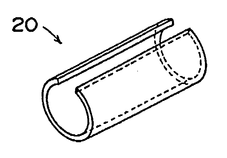
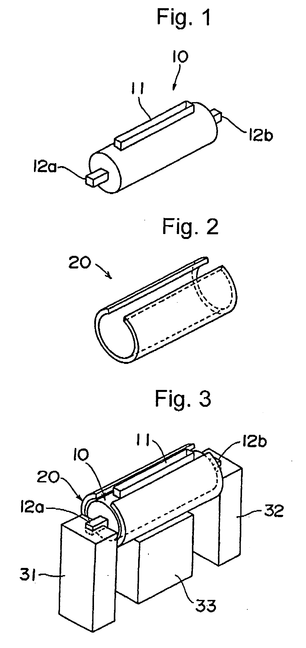
[0010] It is an object of the present invention to provide a reflector capable of covering a heating crucible so that heat in the crucible would be efficiently insulated and evenly distributed.
[0011] It is another object of the invention to provide a combination of a heating crucible and a reflector in which the heating crucible can retain even thermal distribution therein.
[0012] It is still another object of the invention to provide a process for preparing a radiation image storage panel in which bumping of the evaporation source in the vapor-deposition process is prevented effectively enough so as to produce a radiation image storage panel having high sensitivity and giving a reproduced radiation image of high quality.
[0013] The applicant has studied the above-described problems, and finally found that the thermal evenness in the heating crucible can be ensured by the use of an insulating reflector having a shape covering the crucible. The reflector can be combined with the heating crucible and then removed from the heating crucible (which generates heat to work as a heater by itself when electricity is supplied) so as to cancel the uneven thermal distribution in the crucible and, at the same time, to keep the crucible from radiating heat so that the radiated heat would not influence other adjacent crucibles and the substrate onto which the phosphor layer is formed.
[0017] The reflector of the invention has a shape surrounding and covering a heating crucible, and hence can prevent the crucible from radiating heat outside so as to insulate and retain the heat therein. The uneven thermal distribution in the crucible is, therefore, remarkably reduced or minimized to prevent bumping in the vapor-deposition process. In addition, since the crucible is thus kept from radiating heat, the substrate is not so heated and thermal interference among plural crucibles is avoided. Accordingly, it is easy to control the amount of vapor evaporated from each crucible properly enough to form a uniformly deposited layer. Further, since the crucible can be kept from scorching, it can be used for long period of time. Naturally, thermal efficiency of the evaporation-deposition apparatus is improved.
[0018] If the crucible equipped with the reflector of the invention is used in the vapor-deposition process for forming a phosphor layer in producing a radiation image storage panel, the produced storage panel has high sensitivity and gives a reproduced radiation image of high quality.

Problems solved by technology

During the vapor-deposition process for forming the phosphor layer, heat in the heating crucible is often unevenly distributed.
The bumping disturbs formation of the columnar crystals, and the deposited phosphor layer often consists of anomalous columnar crystals and has unfavorable surfaces.
Consequently, the resultant radiation image storage panel gives a radiation image having many point defects.
Further, in the process, the heat radiated from the crucible is liable to elevate the temperature of the substrate (on which the vaporized substance is deposited and accumulated) beyond the predetermined temperature.
Also in that case, anomalous columnar crystals are formed and the resultant storage panel has poor emission properties (for example, in regard to emission intensity).

Method used


Image

  • Reflector, heating crucible equipped with reflector and process for preparation of radiation image storage panel
  • Reflector, heating crucible equipped with reflector and process for preparation of radiation image storage panel
  • Reflector, heating crucible equipped with reflector and process for preparation of radiation image storage panel

Examples


example 1

(1) Evaporation Source

[0076] A powdery cesium bromide (CsBr, purity: 4N or more) and a powdery europium bromide (EuOr2, purity: 3N or more) were prepared. The powdery europium bromide was placed in a platinum crucible, heated to melt at 800° C. in a tube furnace under a halogen gas atmosphere for preventing oxidization, and cooled, Thus melted and cooled EuBr2 and the powdery CsBr were used as the evaporation sources. Each evaporation source was analyzed according to ICP-MS method (Inductively Coupled Plasma Mass Spectrometry), to find impurities. As a result, the CsBr powder contained each of the alkali metals (Li, Na, K, Rb) other than Cs in an amount of 10 ppm or less and other elements such as alkaline earth metals (Mg, Ca, Sr, Ba) in amounts of 2 ppm or less. The melted and cooled EuBr2 contained each of the rare earth elements other than Eu in an amount of 20 ppm or less and other elements in amounts of 10 ppm or less. Those evaporation sources are very hygroscopic, and henc...

example 2

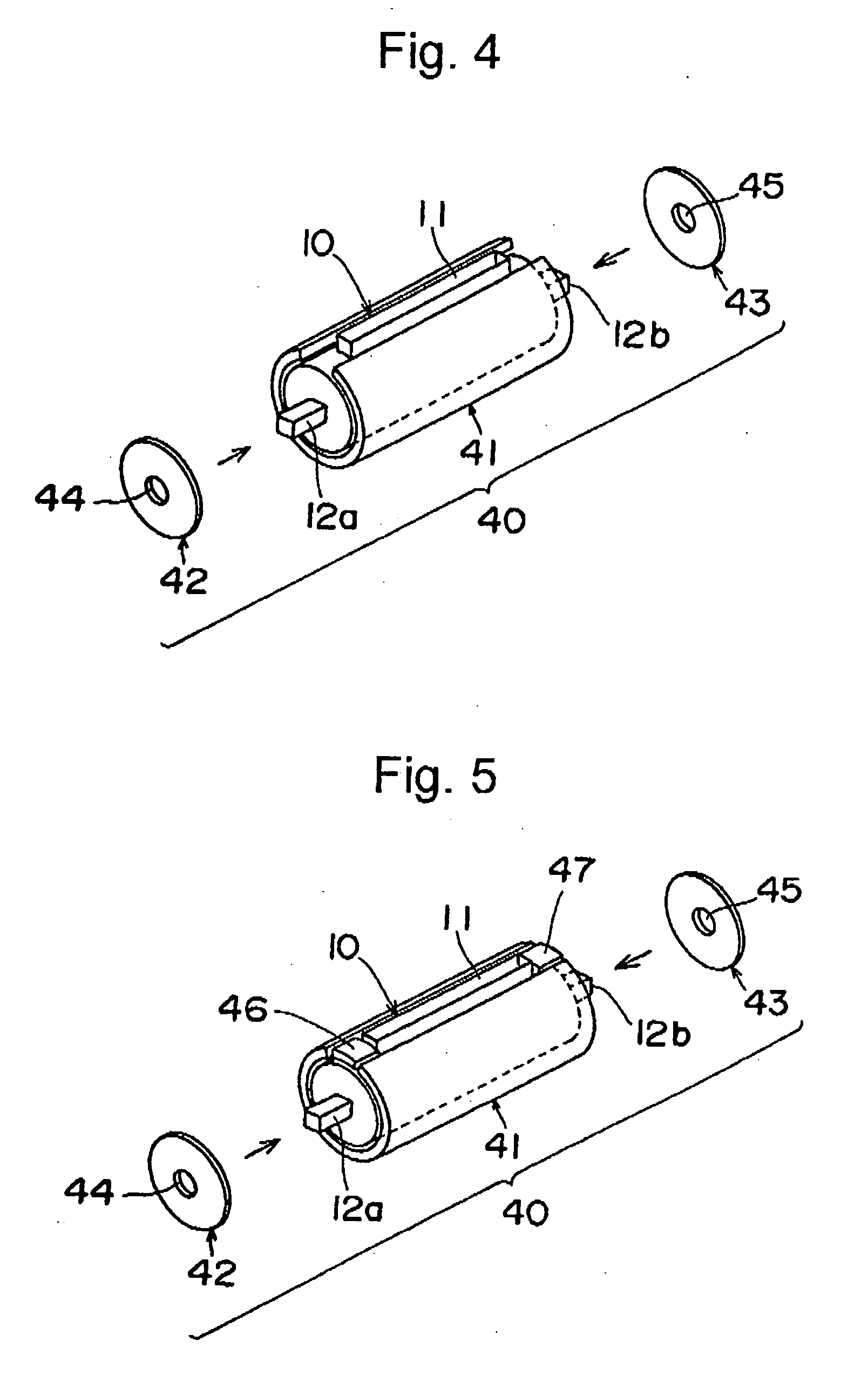
[0080] The procedures of Example 1-(2) were repeated using the combination of the direct resistance-heating crucible and the reflector (as illustrated in FIG. 4, approx. 8% of the outer surface of the crucible was exposed), to prepare a radiation image storage panel of the invention comprising a support and a stimulable phosphor layer.

[0081] In the course of the heating the crucible, the heat distribution in the crucible was examined using thermocouples. It was confirmed that the temperatures in any places of the crucible were within ±1° C. of an average temperature.

example 3

[0082] The procedures of Example 1-(2) were repeated using the combination of the direct resistance-heating crucible and the reflector (as illustrated in FIG. 5, approx. 7% of the outer surface of the crucible was exposed), to prepare a radiation image storage panel of the invention comprising a support and a stimulable phosphor layer.

[0083] In the course of the heating the crucible, the heat distribution in the crucible was examined using thermocouples. It was confirmed that the temperatures in any places of the crucible were within ±1° C. of an average temperature.


PUM

PropertyMeasurementUnit
thicknessaaaaaaaaaa
thicknessaaaaaaaaaa
wavelength regionaaaaaaaaaa

Abstract

A heating crucible which generates heat when electricity is supplied and an insulating reflector having a shape surrounding and covering the crucible is combined.

Description

FIELD OF THE INVENTION [0001] The present invention relates to a reflector covering a heating crucible used for melting and / or vaporizing solid materials, a combination of a heating crucible and the reflector, and a process for preparing a radiation image storage panel utilizing the combination of the heating crucible and reflector. BACKGROUND OF THE INVENTION [0002] For improving thermal efficiency of a high-temperature heating apparatus, a reflector such as a metal plate is generally installed therein so as to insulate and retain heat in the apparatus. For example, JP-A-6-124955 discloses a high-temperature vacuum furnace in which plural reflectors are placed around (namely, above, under and beside) a heater. Those reflectors are made of a metal of a high melting point, such as tantalum (Ta) and molybdenum (Mo). JP-A-2000-150396 further discloses a reflector in the shape of a sheet. The sheet reflector disclosed in the publication comprises metal foil sandwiched between quartz pla...

Claims


Application Information

Patent Timeline
Patent Type & Authority Applications(United States)
IPC IPC(8): B05D3/00B28B11/00C03C17/32
CPCC03C17/22C03C2217/283C03C2218/151C23C14/06Y10T428/1317C23C14/08C23C14/243Y10T428/131C23C14/0694
Inventor NAKASHIMA, TOMOAKINOGUCHI, YUKIHISAKATO, MUNETAKA
Owner FUJIFILM CORP
Learn More