
Traction drive type continuously varible transmission

Inactive Publication Date: 2006-10-05
NTN CORP
View PDF4 Cites 97 Cited by
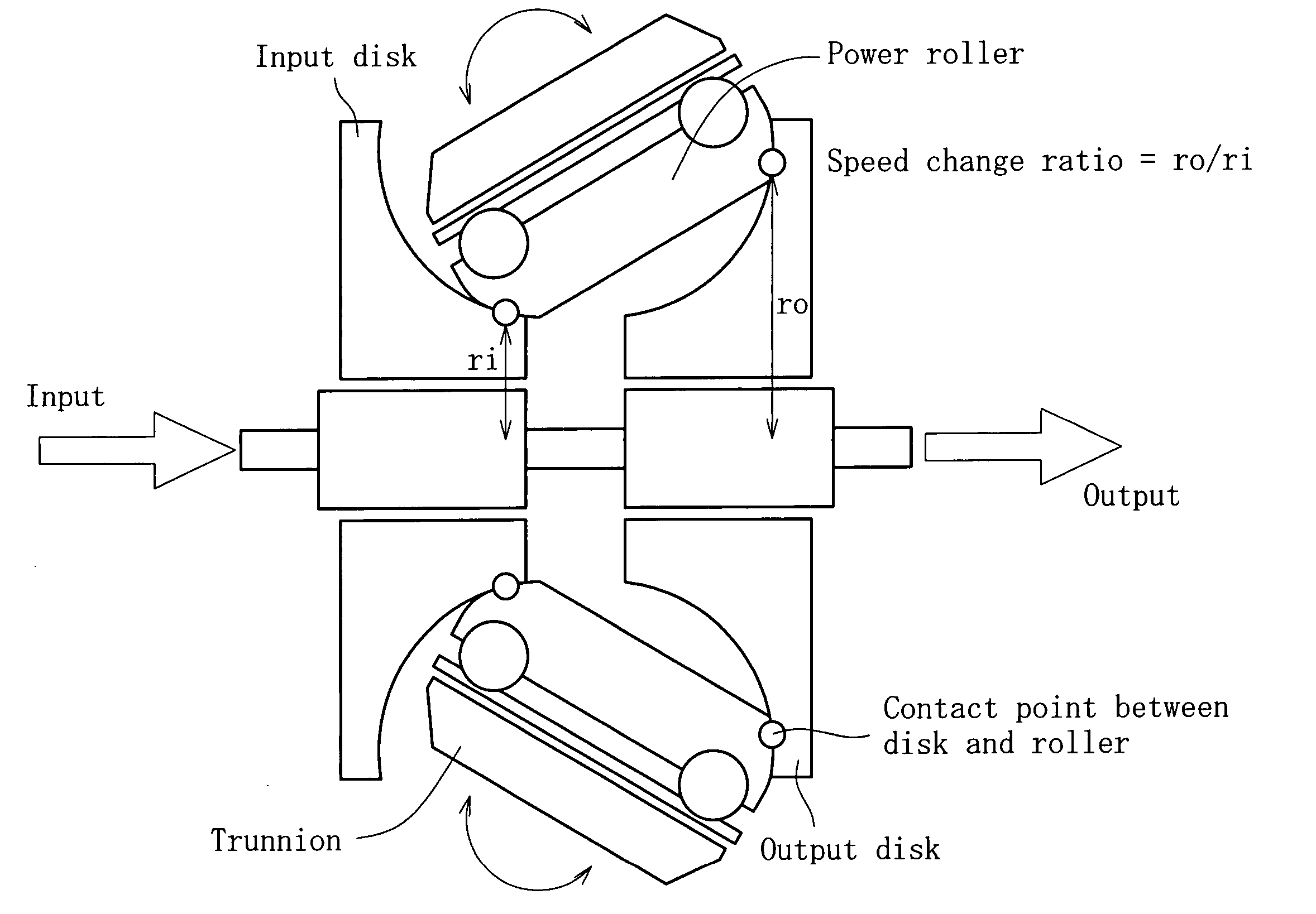
  • Summary
  • Abstract
  • Description
  • Claims
  • Application Information

AI Technical Summary

Benefits of technology

[0004] The problem for traction drive devices is to efficiently transmit large torque with size compaction. To obtain large transmission torque with size compaction, this may be attained by giving a large contact force; however, excessively large contact stress shortens life. To reduce the contact stress, if the device is designed to increase the contact area, the spin component in the contact region increases, lowering the transmission efficiency.
[0005] It is the half toroidal type and metal belt type that have solved these problems to a certain extent, not completely, however, and each has its drawbacks. The half toroidal type swings and changes speed in a state in which a power roller is pressed against an input / output disk surface. A large contact pressure acts thereon, and if no oil film is formed, seizure is caused. Avoiding this needs to improve the surface roughness. Processing a large spherical surface with high accuracy inevitably results in high cost. Further, in the direction of rotation, convexes contact each other, so that a large spin component is produced depending on the contact position, thus lowering the transmission efficiency. Structurally, this type is axially elongated, and cannot be mounted on FF vehicles. On the other hand, the metal belt type is in the form of a stack of a number of elements for easy bending, adapted to be pressed against a V-pulley to transmit torque. Basically, the pulley and the belt are in metal-to-metal contact, so that wear is unavoidable.
[0006] An object of the invention is to provide a traction drive type continuously variable transmission which has solved the above problems and which is capable of efficient transmission of large torque with size compaction.
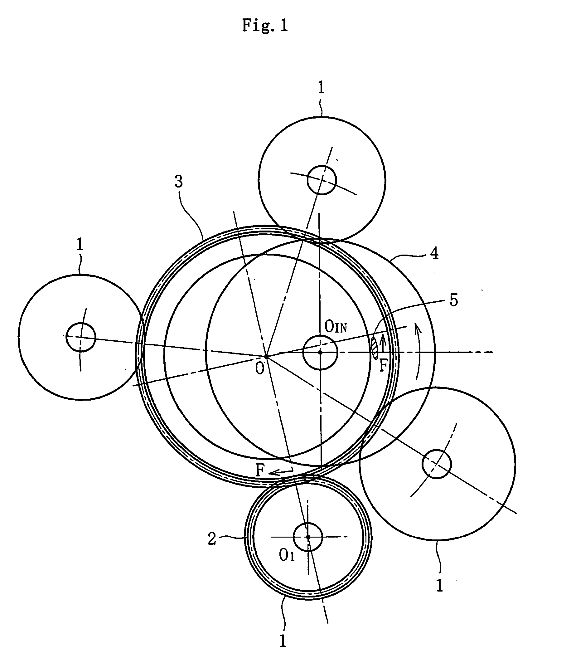
[0008] That is, according to an embodiment of the invention, the traction drive type continuously variable transmission comprises a first input / output shaft rotatably supported by a casing, a second input / output shaft rotatably supported by the casing, a V-pulley consisting of a pair of pulley members supported by the first input / output shaft and having a V-groove whose width is variable, a ring engaged with the V-pulley and supported around its outer periphery, and a mechanism for moving the ring around the axis of the second input / output shaft. As compared with the half toroidal type, the traction drive type continuously variable transmission of the invention has the following advantages. Even if the contact area is increased, the efficiency will be high with little spin component. No spherical processing as in the half toroidal type is required. The transmission is shorter in axial length than in the half toroidal type and applicable to FF vehicles. Further, as compared with the metal belt type, it is simple in construction and has oil films formed in the interface to the pulley, and compared with the metal belt type, no wear is produced, so that it has a long life.

Problems solved by technology

The problem for traction drive devices is to efficiently transmit large torque with size compaction.
To obtain large transmission torque with size compaction, this may be attained by giving a large contact force; however, excessively large contact stress shortens life.
To reduce the contact stress, if the device is designed to increase the contact area, the spin component in the contact region increases, lowering the transmission efficiency.
It is the half toroidal type and metal belt type that have solved these problems to a certain extent, not completely, however, and each has its drawbacks.
A large contact pressure acts thereon, and if no oil film is formed, seizure is caused.
Processing a large spherical surface with high accuracy inevitably results in high cost.
Further, in the direction of rotation, convexes contact each other, so that a large spin component is produced depending on the contact position, thus lowering the transmission efficiency.
Structurally, this type is axially elongated, and cannot be mounted on FF vehicles.
Basically, the pulley and the belt are in metal-to-metal contact, so that wear is unavoidable.

Method used


Image

  • Traction drive type continuously varible transmission
  • Traction drive type continuously varible transmission
  • Traction drive type continuously varible transmission

Examples


Embodiment Construction

[0034] Embodiments of the invention will now be described with reference to the accompanying drawings.

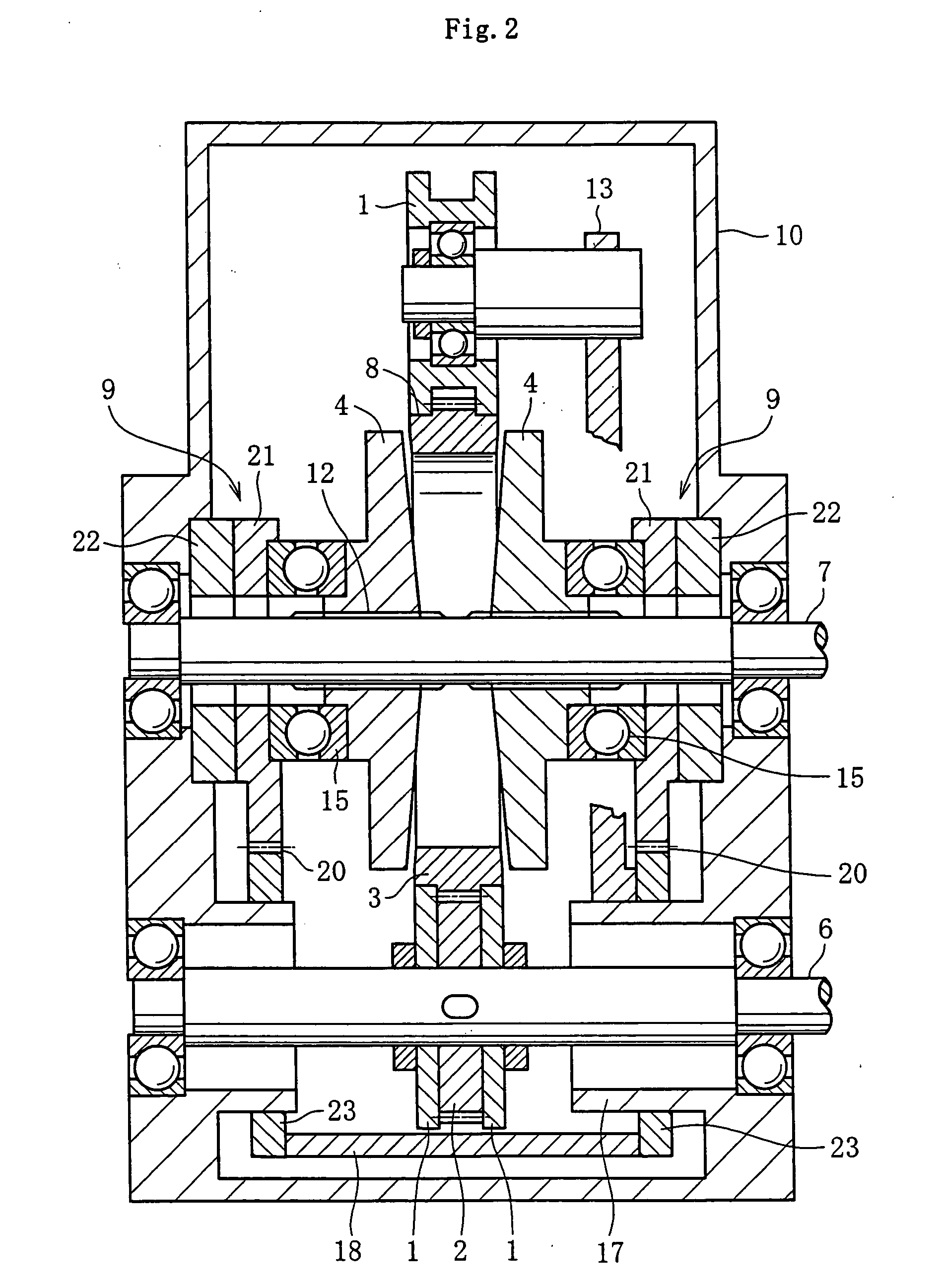
[0035]FIG. 2 is a sectional view of a traction drive type continuously variable transmission, showing an embodiment of the invention. As can be seen from the figure, it is of a construction in which a ring 3 is fitted in the groove of a V-pulley consisting of a pair of axially movable pulley members 4. In this embodiment, the ring 3 has gear teeth around its outer periphery; therefore, it will be hereinafter referred to as the toothed ring. As shown in FIG. 2, input / output shafts 6 and 7 which are parallel with each other are rotatably supported through their respective bearings in a casing 10. In this embodiment, torque transmission is effected between these two shafts 6 and 7, and their relation is such that if one shaft (6 or 7) is an input shaft, the other shaft (7 or 6) becomes an output shaft.

[0036] The first input / output shaft 6 has an input / output gear 2 fixed thereto. The...


PUM


Abstract

A traction drive type continuously variable transmission, comprising a first input / output shaft (6) rotatably supported on a casing (10), a second input / output shaft (7) rotatably supported on the casing (10), a V-pulley (4) supported on the first input / output shaft (6) and having a pair of pulley members forming a V-groove with variable grove width, a ring (3) engaged with the V-pulley (4) and supported at the outer periphery thereof, and a mechanism for moving the ring (3) to the periphery of the second input / output shaft (7).

Description

CROSS-REFERENCE TO RELATED APPLICATION [0001] This application is a National Stage entry of International Application No. PCT / JP2004 / 001156, filed Feb. 4, 2004, the entire specification claims and drawings of which are incorporated herewith by reference.TECHNICAL FIELD [0002] This invention relates to a traction drive type continuously variable transmission used in automobiles and various industrial machines. Background Art [0003] Many inventions have heretofore been made concerning the continuously variable transmission (CVT). Recently, the half toroidal type (FIG. 4) has gained attention; however, the direction of practicality is toward the use of a metal belt type (FIGS. 5a and 5b). Reference: “Development of Traction Drive Type Continuously Variable Transmission, Second Report—Comparison between Half Toroidal CVT and Full Toroidal CVT,” NSK Technical Journal No. 670 (2000), Nippon Seiko K. K., pp. 2-10. DISCLOSURE OF THE INVENTION [0004] The problem for traction drive devices is...

Claims


Application Information

Patent Timeline
IPC IPC(8): F16H15/38F16H15/22F16H37/02F16H55/56
CPCF16H15/22F16H55/56F16H37/021
Inventor NAKAZEKI, TSUGITO
Owner NTN CORP
Learn More