Surface modification method for inorganic oxide powder, powder produced by the method and use of the powder

Inactive Publication Date: 2006-06-15
SHOWA DENKO KK
View PDF4 Cites 13 Cited by
  • Summary
  • Abstract
  • Description
  • Claims
  • Application Information

AI Technical Summary

Benefits of technology

[0012] The present inventors have performed extensive studies and, as a result have found that, when powder consisting of large-size particles (hereinafter may be referred to as “powder A”) and powder consisting of small-size particles (hereinafter may be referred to as “powder B”) are simultaneously brought into a high-temperature flame, to thereby deposit or bond particles of the powder B to the surfaces of particles of the powder A, or when inorganic oxide powder (hereinafter may be referred to as “powder A”) is brought into a high-temperature flame formed by use of a combustible gas and a combustion-supporting gas, and the resultant powder is again brought into the high-temperature flame, to thereby modify the surface of the powder, there can be produced a powder product which, when kneaded with a highly viscous composition (e.g., an organic polymer composition or a silicon-containing polymer composition), exhibits the effect of reducing the viscosity of the composition to a very low level. The present invention has been accomplished on the basis of this finding.

Problems solved by technology

However, in a conventional technique, a process for producing spherical powder of high fillability is separated from a process for surface treatment of the powder, leading to very low productivity and high production cost.
Although production of spherical powder requires high-temperature thermal treatment, a conventional surface treatment agent undergoes decomposition at high temperature, and thus difficulty is encountered in carrying out production of the powder and surface treatment thereof in a single process.

Method used


Image

  • Surface modification method for inorganic oxide powder, powder produced by the method and use of the powder
  • Surface modification method for inorganic oxide powder, powder produced by the method and use of the powder
  • Surface modification method for inorganic oxide powder, powder produced by the method and use of the powder

Examples


example 1

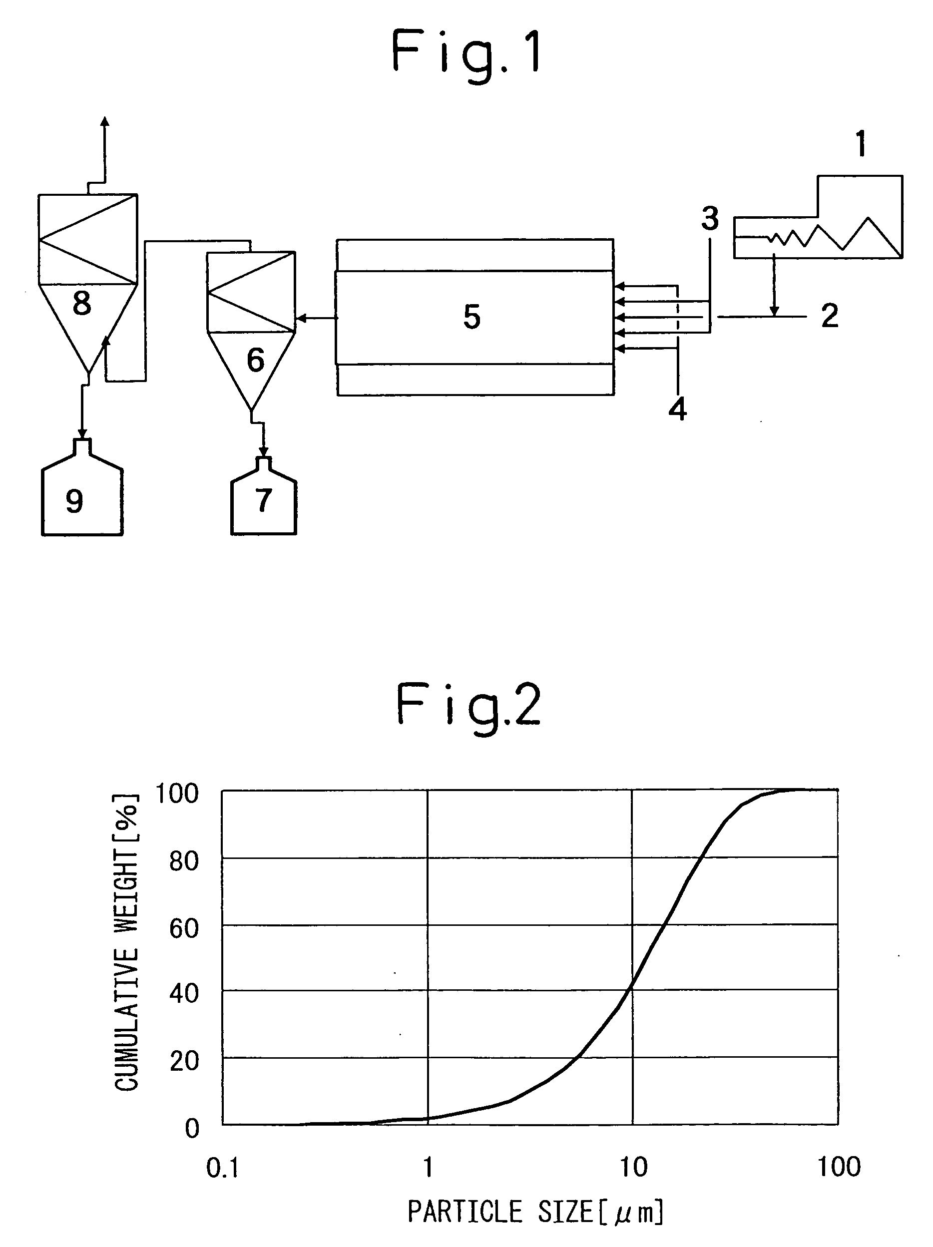
[0084] Gaseous titanium tetrachloride (concentration: 100%) was preliminarily heated to 1,000° C. Separately, a gas mixture of oxygen (96 vol. %) and steam (4 vol. %) was preliminarily heated to 1,000° C. The titanium tetrachloride gas and the gas mixture were brought into a reaction tube through a coaxial parallel-flow nozzle at flow rates of 45 m / second and 50 m / second, respectively. The titanium tetrachloride gas was fed through the inner tube. The flow rates of the titanium tetrachloride gas and the gas mixture in the reaction tube were found to be 8 m / second (calculated value) at a reaction temperature of 1,630° C. Cooling air was brought into the reaction tube such that the high-temperature residence time of the resultant reaction mixture was 0.1 seconds or less in the reaction tube. Thereafter, the thus-produced titanium dioxide powder was collected by use of a polytetrafluoroethylene-made bag filter.

[0085] The thus-produced titanium dioxide powder was found to have a BET-ba...

example 2

[0091] Gaseous aluminum chloride which had been diluted with nitrogen (concentration of aluminum chloride: 60%) was heated to 1,000° C. Separately, a gas mixture of oxygen (40 vol. %) and steam (60 vol. %) was heated to 1,000° C. The aluminum chloride gas and the gas mixture were brought into a reaction tube through a coaxial parallel-flow nozzle at flow rates of 40 m / second and 30 m / second, respectively. The aluminum chloride gas was fed through the inner tube. After completion of reaction, cooling air was brought into the reaction tube such that the high-temperature residence time of the resultant reaction mixture was 0.1 seconds or less in the reaction tube. Thereafter, the thus-produced alumina powder was collected by use of a polytetrafluoroethylene-made bag filter.

[0092] The thus-produced aluminum oxide powder was found to have a BET-based particle size of 37 nm and to predominantly contain a δ-alumina crystal phase. The aluminum oxide powder was employed as powder B (raw mat...

example 3

[0097] Gaseous aluminum chloride which had been diluted with nitrogen (concentration of aluminum chloride: 26%) was preliminarily heated to 1,000° C. Separately, a gas mixture of oxygen (35 vol. %) and steam (65 vol. %) was preliminarily heated to 1,000° C. The aluminum chloride gas and the gas mixture were brought into a reaction tube through a coaxial parallel-flow nozzle at flow rates of 61 m / second and 55 m / second, respectively. The aluminum chloride gas was fed through the inner tube. After completion of reaction, cooling air was brought into the reaction tube such that the high-temperature residence time of the resultant reaction mixture was 0.1 seconds or less in the reaction tube. Thereafter, the thus-produced alumina powder was collected by use of a polytetrafluoroethylene-made bag filter.

[0098] The thus-produced aluminum oxide powder was found to have a BET-based particle size of 15 nm and to predominantly contain a γ-alumina crystal phase. The aluminum oxide powder was e...


PUM

PropertyMeasurementUnit
Lengthaaaaaaaaaa
Percent by massaaaaaaaaaa

Abstract

A surface modification method comprising bringing, into a high-temperature flame formed by use of a combustible gas and a combustion-supporting gas, inorganic oxide powder A having an average particle size falling within a range of 0.5 to 200 μm as measured by means of laser diffraction / scattering particle size analysis and inorganic oxide powder B having a particle size calculated on the basis of its BET specific surface area of 100 nm or less, to thereby modifiy the surfaces of particles of the powder A by means of the particles of the powder B. A surface modification method comprising bringing, into a high-temperature flame formed by use of a combustible gas and a combustion-supporting gas, the inorganic oxide powder A; and bringing again the resultant powder into the high-temperature flame, to thereby modify the surfaces of particles of powder A.

Description

CROSS REFERENCE TO RELATED APPLICATION [0001] This application is an application filed under 35 U.S.C. §111(a) claiming benefit pursuant to 35 U.S.C. §119(e)(1) of the filing date of the Provisional Application No. 60 / 443,529 filed on Jan. 30, 2003, pursuant to 35 U.S.C. §111(b).TECHNICAL FIELD [0002] The present invention relates to a method for modifying the surfaces of inorganic oxide particles; to powder obtained through the method, which exhibits excellent fillability, thermal conductivity, viscosity characteristics, and fluidity; and to use of the powder. BACKGROUND ART [0003] Conventionally, inorganic oxide powder has been employed as, for example, a filler for imparting to an object characteristics such as reinforcement, flame retardancy, high thermal conductivity, and insulating property, a filler for a semiconductor sealing material, a viscosity adjusting agent, a fluidity improving agent, or a charge regulating agent; or has been employed in, for example, a coating materi...

Claims


Application Information

Patent Timeline
IPC IPC(8): C09K11/77B32B5/16C09C1/36C09C3/06
CPCB82Y30/00C01P2004/62C01P2004/64C01P2004/82C01P2006/12Y10T428/2991C09C1/407C09C3/063C01P2004/51C01P2004/04C01P2006/22C09C1/3661
Inventor KOGOI, HISAOTANAKA, JUN
Owner SHOWA DENKO KK
Why Eureka
Try Eureka