
Electronic part with external electrode

a technology of electronic parts and electrodes, applied in the direction of non-metal conductors, conductors, fixed capacitor details, etc., can solve the problems of poor plating adhesion, cracks, and reliability of capacitor performance, and achieve excellent bonding properties and high melting points

Active Publication Date: 2006-03-02
NAMICS CORPORATION +1
View PDF12 Cites 66 Cited by
  • Summary
  • Abstract
  • Description
  • Claims
  • Application Information

AI Technical Summary

Benefits of technology

[0014] The thermosetting conductive paste comprises metal powder having a melting point of 300° C. or less in addition to conventional conductive particles having a high melting point, and thus the solid-phase diffusion of the conductive particles in the conductive paste into internal electrode metal can progress even at a low curing temperature of about 80° C. to 400° C., thereby excellent bonding-property between the internal electrode(s) and the external electrode(s) can be obtained.

Problems solved by technology

However, a capacitor having an external electrode(s) obtained by the first method above has, for example, the problem of poor plating-adhesion due to the floating of glass, because of the diffusion of the glass-frit component in the conductive paste into the inside of a capacitor element when the capacitor is fired at an elevated temperature, and the problem of the occurrence of cracks when the capacitor is mounted with solder on a substrate.
Furthermore, it has problems concerning the reliability of capacitor performance.
For example, due to the infiltration of a plating solution into a sintered body in the plating-treatment, the electric capacitance is lower than a designed value, and / or the insulation resistance is deteriorated.
However, because of its low curing temperature, the metal-to-metal solid-phase diffusion of the conductive particles (such as silver powder) in the conductive paste into the internal electrode(s) can not progress, and thus the junction of the internal electrode(s) with the external electrode(s) is poor, thereby its designed electrical properties such as electric capacity can not be obtained, and thus the resultant capacitor is poor in the reliabilities.
Furthermore, a capacitor having an external electrode(s) formed by the third method, wherein the thermosetting conductive paste containing the pyrolytic organometallic material(s) is used, has such problems as the insulation deterioration for its moisture-resistible duration of life and the pot life of the paste is shortened, due to silver acetate and amine added to the paste.

Method used


Image

  • Electronic part with external electrode
  • Electronic part with external electrode

Examples


example 1

Preparation of Thermosetting Electrode

[0044] A thermosetting conductive paste (C) as shown in Table 1 was applied, dried, cured and plated under conditions in Comparative Example 2 so as to obtain a chip multilayer capacitor.

[Measurement]

[0045] Each chip multilayer capacitor element obtained in the above was put on a Pb-free solder paste which had been printed on a copper-clad electrode of a glass-epoxy substrate. The capacitor element was solder-jointed with the substrate electrode at a temperature at which the solder paste was sufficiently fused, for example, at a temperature of 250 to 260° C. so as to be used as a test sample for the electric properties and the bonding strength. The initial electric properties (electric capacitance, tanδ) of the sample were determined by means of a 4278A manufactured by Agilent, and the bonding strength (shear strength) of the capacitor element to the substrate electrode was determined by means of a bonding strength-testing machine manufacture...

examples 1a to 1d

[0048] In order to examine a case wherein each content of conductive particles having a high melting point and metal powder having a melting point of 300° C. or less in a thermosetting conductive paste is modified, a thermosetting conductive paste in a manner similar to the one described above was prepared with a composition as shown in the following Table 3. The total content of the conductive particles having a high melting point and the metal powder having a melting point of 300° C. or less in the thermosetting conductive paste was 60 to 98% by weight relative to the total weight of the conductive particles having a high melting point, the metal powder having a melting point of 300° C. or less and a resin(s). Furthermore, a capacitor sample was prepared with each of the prepared pastes in a manner similar to the one described in Example 1 so as to determine the electric properties and the bonding strength.

[0049] The capacitor obtained in each of Examples 1a to 1d was excellent i...

examples 1e to 1g

[0050] In order to examine a case wherein the content of metal powder having a melting point of 300° C. or less in a thermosetting conductive paste is modified, a thermosetting conductive paste was prepared with a composition as shown in the following Table 4 in a manner similar to the one described above. The content of the metal powder having a melting point of 300° C. or less in the paste was 1 to 25% by weight relative to the total weight of the conductive particles having a high melting point and the metal powder having a melting point of 300° C. or less. Furthermore, a capacitor sample was prepared with each of the prepared pastes in a manner similar to the one described in Example 1 so as to determine the electric properties and the bonding strength.

[0051] The capacitor obtained in each of Examples 1e to 1 g was excellent in electric properties and bonding strength just like the one described in Example 1. In particular, when the content (i.e. Ratio of Tin Powder to Total Me...


PUM


Abstract

The present invention is intended to solve the problem of a conventional thermosetting conductive paste with respect to bonding-property between an internal electrode(s) and an external electrode(s) so as to provide a multilayer ceramic electronic part suitable for its mounting on a substrate and for its plating-treatment. The present invention relates to a multilayer ceramic electronic part, characterized in that it has an external electrode(s) formed from a thermosetting conductive paste comprising conductive particles having a high melting point, metal powder having a melting point of 300° C. or less and a resin(s).

Description

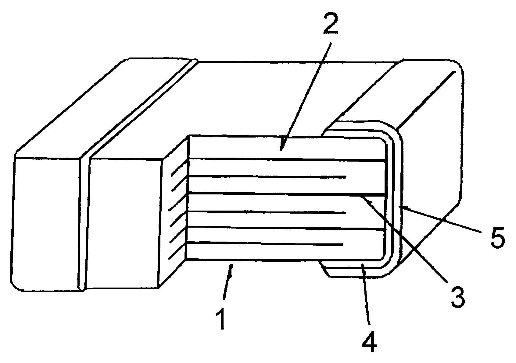
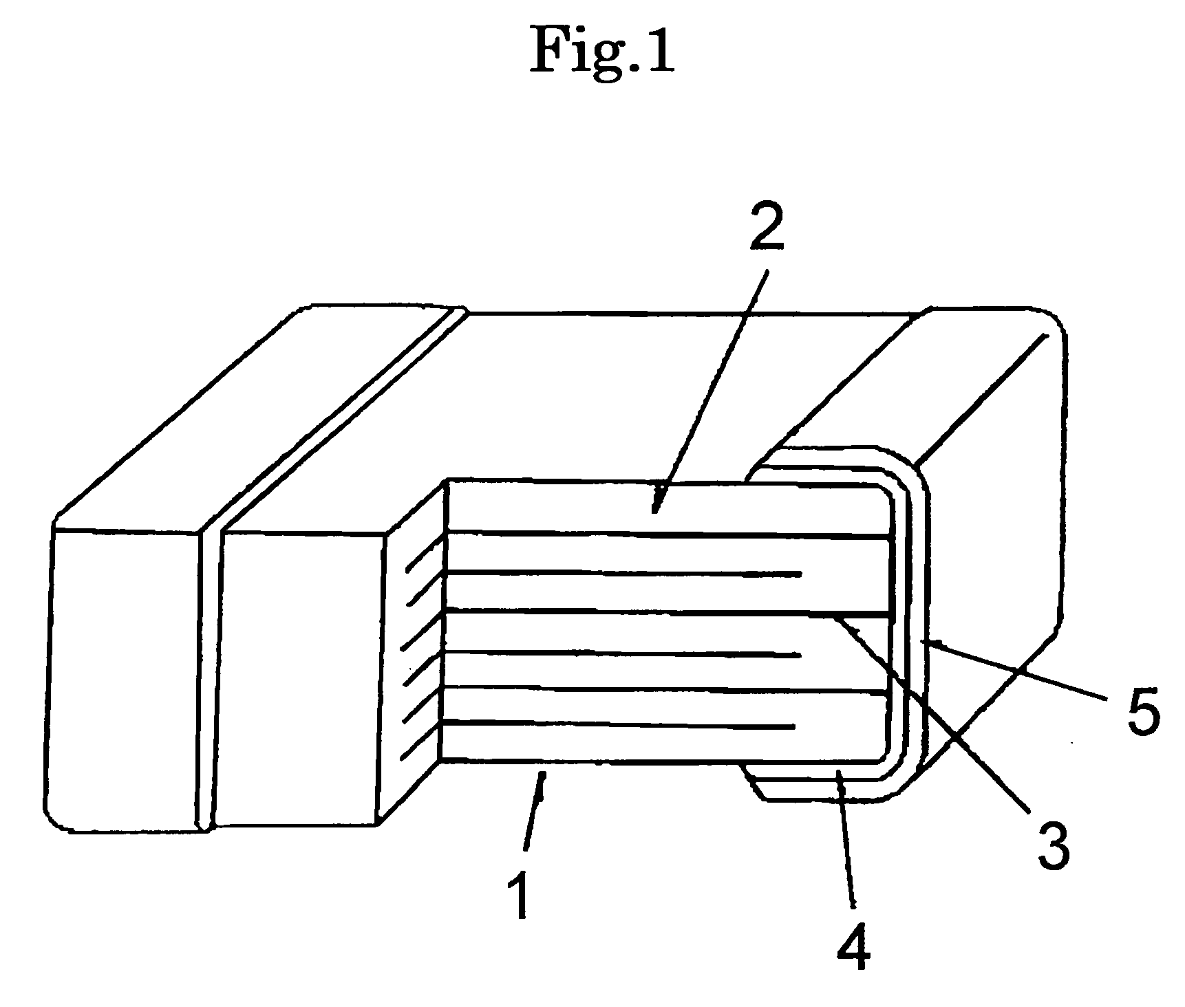
TECHNICAL FIELD [0001] The present invention relates to a multilayer ceramic electronic part, in particular to a highly reliable multilayer ceramic electronic part such as a multilayer ceramic capacitor, which is suitable for its mounting on a substrate or for its plating treatment. BACKGROUND ART [0002] A multilayer ceramic capacitor which is one example of multilayer ceramic electronic parts is illustrated in FIG. 1, wherein an external electrode (4) formed on a surface where an internal electrode(s) of a ceramic composite body of the multilayer ceramic capacitor (1) is led out is generally formed by using a fired-type conductive paste or a thermosetting conductive paste according to a method as described below, wherein the ceramic composite body comprises a ceramic dielectric(s) (2) and the internal electrode(s) (3), as alternately layered. [0003] The first method is the one for forming an external electrode (4) by applying a fired-type conductive paste to a surface where an inte...

Claims


Application Information

Patent Timeline
IPC IPC(8): H01F21/04H01B1/22H01G4/232
CPCH01B1/22H01G4/005H01G4/2325
Inventor KIMURA, TAKESHITAKADA, YAMATOKOMAGATA, MICHINORIKITAMURA, MASAHIROYOKOYAMA, KIMNORI
Owner NAMICS CORPORATION
Learn More