Underbalanced drilling method and apparatus
a drilling method and equipment technology, applied in the direction of drilling rods, drilling pipes, borehole/well accessories, etc., can solve the problems of preventing overbalanced drilling, affecting the production of wells, so as to achieve cost-effectiveness, reduce the loss of production due to formation, and reduce the effect of overbalanced drilling
- Summary
- Abstract
- Description
- Claims
- Application Information
AI Technical Summary
Benefits of technology
Problems solved by technology
Method used
Image
Examples
first embodiment
[0051] Referring to the FIG. 1, there is depicted a drilling rig 40 and an outlay of component parts of an above the ground system 50 which may be included with the drilling rig to practice an underbalanced drilling method of this invention. A well bore 20 is drilled through the permeable formation 22, and a formation fluid 23 is gas. A casing 24 is placed above formation 22. The well bore has an open hole section 21. A drill string 26 comprises a series of interconnected joints of drill pipe with a through bore. A blow out preventer stack comprises a rotating blowout preventer (RBOP) 28. A drill bit 30 is attached to the drill string. The drill string may comprise a Measurement While Drilling (MWD) device 32 which is capable to provide information comprising the bottom hole pressure.
[0052] Drilling rig 40 may comprise a rotary table 42. A top drive 44 may be provided for rotating the drill string. The drilling rig may comprise a mud pump 46 and a drilling fluids handling facility 4...
second embodiment
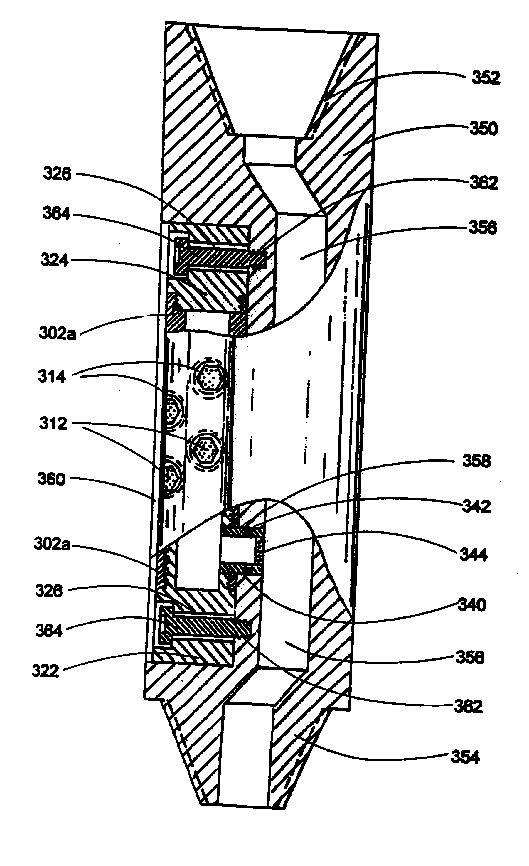
[0144]FIGS. 9 and 10 show the of the adjustable lifting gas injector (LGI). In this embodiment LGI comprises a flow regulator 320 and a side pocket sub 350.
[0145] Referring to the FIG. 9, flow regulator 320 comprises a tubular member 302a with at least one of a plurality of openings 310. The openings are adopted to include a porous insert 312 or a plug of the same shape (not shown). Inserts and plugs may be kept in place by a threaded retainer 314. Openings 310 with porous inserts and plugs constitute an inlet port of LGI. A check valve 330 is mounted inside the tubular member and is kept in place with a threaded lower plug 322. Lower plug 322 and an upper plug 324 seal the tubular member which is thereafter referred to as a housing 302a of the flow regulator. Each plug may comprise a bore 326 for placing a bolt (not shown in FIG. 8).
[0146] A connecting pipe 340 is mounted into a side opening 341 of housing 302a below the check valve.
[0147] A check valve 330 may comprise a housing...
third embodiment
[0153]FIG. 11 depicts a remotely controlled flow regulator 400 which is adopted to be mounted in the side pocket of the sub as it has been described above for flow regulator 320 with reference to FIG. 10. Flow regulator 400 together with the side pocket sub described above constitutes the lifting gas injector of the invention.
[0154] Remotely controlled flow regulator 400 comprises a housing 402, a check valve 330, a connecting pipe 340, plugs 322, 324, a piston 406, a power unit 410, a bearing 412.
[0155] The housing may comprise a plurality of side openings 310. The openings are adopted to include a porous insert 312. Inserts may be kept in place by a threaded retainer 314. Side openings with porous inserts constitute the inlet port of the flow regulator. The way of choosing the number and area of side openings as well as choosing permeability coefficient of inserts is the same as it was disclosed above with reference to FIG. 8
[0156] A check valve 330 may comprise a housing 332 wit...
PUM
 Abstract
Description
Claims
Application Information
 - R&D
- Intellectual Property
- Life Sciences
- Materials
- Tech Scout
- Unparalleled Data Quality
- Higher Quality Content
- 60% Fewer Hallucinations
Browse by: Latest US Patents, China's latest patents, Technical Efficacy Thesaurus, Application Domain, Technology Topic, Popular Technical Reports.
© 2025 PatSnap. All rights reserved.Legal|Privacy policy|Modern Slavery Act Transparency Statement|Sitemap|About US| Contact US: help@patsnap.com


