
Mask blank and mask for electron beam exposure

Inactive Publication Date: 2005-12-01
HOYA CORP
View PDF5 Cites 12 Cited by
  • Summary
  • Abstract
  • Description
  • Claims
  • Application Information

AI Technical Summary

Benefits of technology

[0017] Therefore, it is an object of this invention to obtain a pattern support layer having a thin thickness wherein a time-dependent change in stress is small.

Problems solved by technology

In the lithography technology for forming wiring patterns and so on, as patterns to be formed become extremely finer and finer, the pattern formation becomes difficult in the conventional optical lithography technology that is used as a general purpose technology.

Method used


Image

  • Mask blank and mask for electron beam exposure
  • Mask blank and mask for electron beam exposure
  • Mask blank and mask for electron beam exposure

Examples


Embodiment Construction

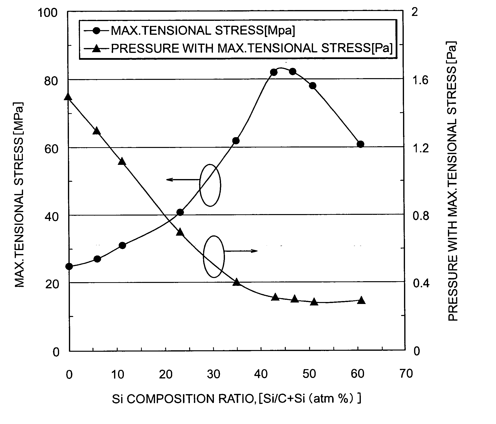
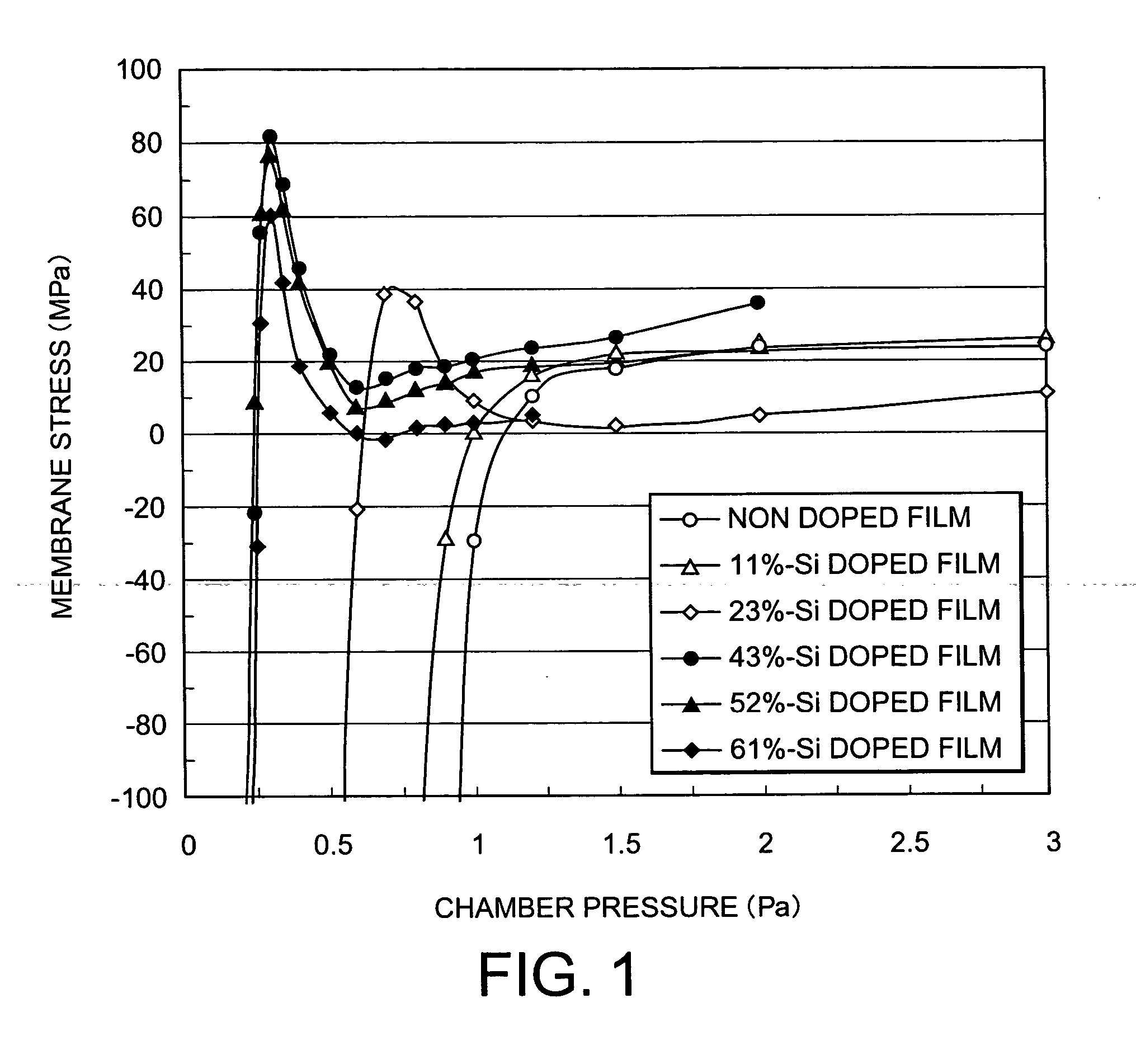
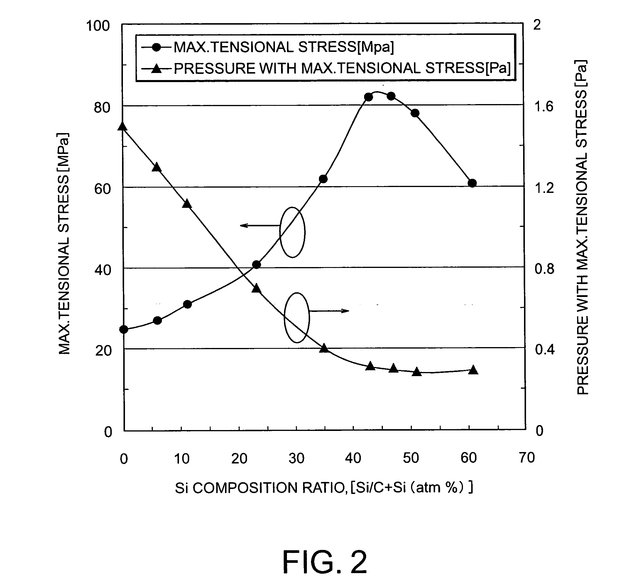
[0058] FIGS. 1 to 6 show the results of evaluating pattern support layers each of which is formed as a membrane of a mixture of carbon and silicon on a support body of a Si substrate by a sputtering method carried out in a multi-cathode system by the use of Ar gas. In the pattern support layers, materials of the membranes have different Si contents (% represents atm % in the figures) relative to C. As a comparison, the results of evaluating a DLC film formed by Ar sputtering by using a carbon target is simultaneously shown.

[0059] First, FIG. 1 shows a relationship between a membrane stress and a deposition pressure with respect to each of the foregoing pattern support layers. On the other hand, FIG. 2 shows maximum tensional stresses relative to changes in addition amount of Si and deposition pressures when those maximum tensional stresses are obtained, with respect to the foregoing pattern support layers. From the results of FIGS. 1 and 2, it is understood that as the content of S...


PUM

PropertyMeasurementUnit
Thicknessaaaaaaaaaa
Thicknessaaaaaaaaaa
Nanoscale particle sizeaaaaaaaaaa

Abstract

A mask blank for electron beam exposure includes a pattern support layer that transmits an electron beam therethrough, an electron beam scattering layer formed on the pattern support layer, and a support body supporting the pattern support layer and the electron beam scattering layer. The pattern support layer is formed by a material that has an amorphous structure and that is mainly composed of carbon-silicon bonds. The pattern support layer is a tensional stress membrane that has a surface roughness of 0.2 (nm, Rms) or less. A mask for electron beam exposure is formed by patterning the electron beam scattering layer of the mask blank.

Description

CROSS REFERENCE TO RELATED APPLICATION [0001] This application claims the benefit of U.S. Provisional Application No. 60 / 574,935 filed May 28, 2004.BACKGROUND OF THE INVENTION [0002] This invention relates to a mask blank and a mask and, in particular, relates to a mask blank and a mask for electron beam exposure. [0003] In the lithography technology for forming wiring patterns and so on, as patterns to be formed become extremely finer and finer, the pattern formation becomes difficult in the conventional optical lithography technology that is used as a general purpose technology. Therefore, a serious investigation has been directed to an exposure technique using a short-wavelength beam, like a charged particle beam such as an electron beam or an ion beam, an X-ray, or the like so as to achieve further finer pattern formation. Among them, the direct-write electron beam technique has been developed from initial point beam writing, then a variable shaping projection method that perfor...

Claims


Application Information

Patent Timeline
IPC IPC(8): B32B9/00B32B15/00B32B17/06G03C5/00G03F1/20G03F1/60H01L21/027
CPCG03F1/20
Inventor AMEMIYA, ISAO
Owner HOYA CORP
Learn More