
Etching system and method for treating the etching solution thereof

a technology of etching system and etching solution, which is applied in the direction of electrical equipment, decorative surface effects, decorative arts, etc., can solve the problems of increasing the difficulty in controlling process parameters, affecting the stability of etching selectivity, and affecting the quality of etching, etc., to achieve stable etching selectivity and reduce the cost of the etching process dramatic

Inactive Publication Date: 2005-12-01
PROMOS TECH INC
View PDF11 Cites 30 Cited by
  • Summary
  • Abstract
  • Description
  • Claims
  • Application Information

AI Technical Summary

Benefits of technology

[0014] The objective of the present invention is to provide an etching system and a method for treating the etching solution with a stable selectivity between silicon nitride and silicon oxide.
[0017] Compared with the prior art, the present invention possesses a steadier, smaller variation of the silicon concentration in the etching solution, and achieves a stable etching selectivity between the silicon nitride and silicon oxide. In addition, the present invention need not drain the used etching solution, which can reduce the cost of the etching process dramatically.

Problems solved by technology

For example, a 0.2 μm silicon particle remaining on the surface of wafer 10 will seriously cause integrated circuit fabricated by a 0.13 μm MOS fabrication process to fail.
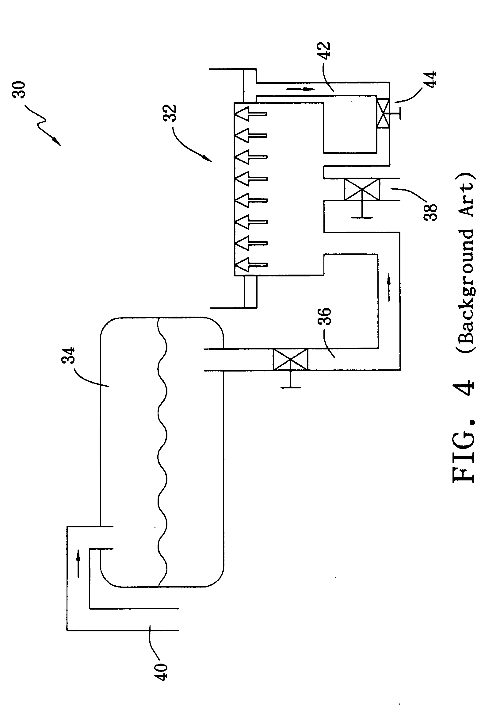
However, if there were too many silicon particles, the filter 44 would easily fail due to the blocking of the silicon particles.
Therefore, the etching selectivity between silicon nitride and silicon oxide also changes with the processing time of the etching solution, which further increases the difficulty to control the process parameters, such as the etching time.
However, this treating method obviously reduces the efficiency of the etching solution.
Furthermore, completely renewing the phosphoric acid etching solution increases the consumption of phosphoric acid and raises the etching cost.

Method used


Image

  • Etching system and method for treating the etching solution thereof
  • Etching system and method for treating the etching solution thereof
  • Etching system and method for treating the etching solution thereof

Examples


Embodiment Construction

[0026]FIG. 7 shows the relation between the silicon concentration and both the etching rate and silicon particle concentration in the etching solution. Curve 72 represents the etching curve of silicon nitride, curve 74 represents the etching curve of silicon oxide, and curve 76 is a variation curve of the silicon particle concentration. As shown in FIG. 7, the etching rate of silicon nitride is substantially not influenced by the silicon concentration virtually and is fixed at about 90 Å / min. In contrary, the etching rate of silicon oxide reduces as the silicon concentration increases, and is fixed at about 0.2 Å / min as the silicon concentration is above 100 ppm. When the silicon concentration is above 100 ppm, the silicon particle concentration of the etching solution increases as the silicon concentration increases.

[0027]FIG. 8 shows the relation between the silicon saturation concentration of the etching solution (i.e. the solubility of silicon in the etching solution) and the t...


PUM

PropertyMeasurementUnit
temperatureaaaaaaaaaa

Abstract

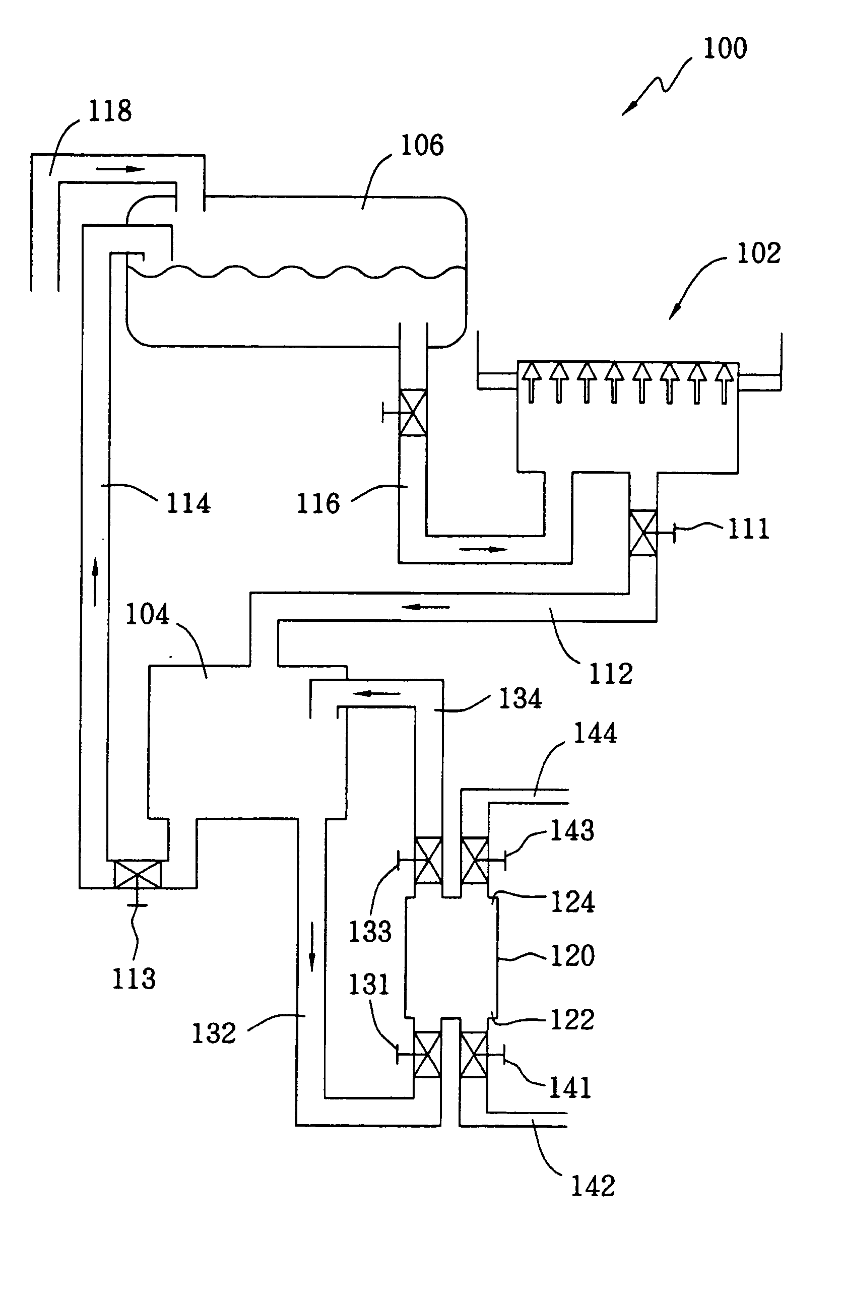
The present etching system includes a processing tank with an etching solution containing silicon, a cooling tank, a pre-heating tank, a first pipe for transferring the etching solution from the processing tank to the cooling tank, a second pipe for transferring the etching solution from the cooling tank to the pre-heating tank, and a third pipe for transferring the etching solution from the pre-heating tank to the processing tank. The present method for treating the etching solution first performs an etching process using the etching solution, which is then cooled to a first temperature to form a silicon-saturated etching solution. After silicon-containing particles larger than a predetermined size are filtered out, the silicon-saturated etching solution is heated to a second temperature to form a non-saturated etching solution for performing another etching process later. The second temperature is preferably at least 10° C. higher than the first temperature.

Description

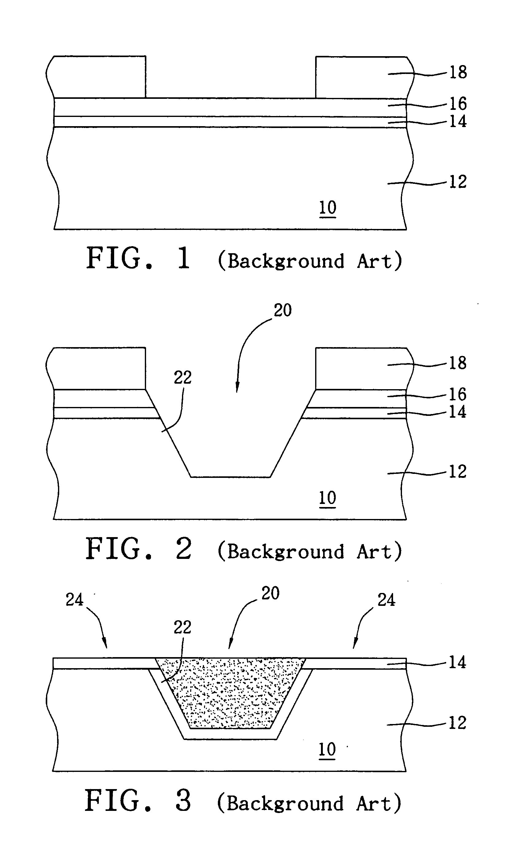
BACKGROUND OF THE INVENTION [0001] (A) Field of the Invention [0002] The present invention relates to an etching system and method for treating the etching solution thereof, and more particularly, to an etching system and a method for treating the etching solution with a stable selectivity between silicon nitride and silicon oxide. [0003] (B) Description of the Related Art [0004]FIG. 1 to FIG. 3 show a method for fabricating a shallow trench isolation on a wafer 10 according to the prior art. The shallow trench isolation is widely used in the fabrication of the metal-oxide-semiconductor (MOS) transistor to form an electrical isolation between transistors. As shown in FIG. 1, the fabrication of the shallow trench isolation begins to form an oxide layer 14, a silicon nitride layer 16 and a photoresist layer 18 in sequence on a silicon substrate 12, and the pattern of the active region 24 is then transformed from an active region mask to the photoresist layer 18. [0005] Referring to FI...

Claims


Application Information

Patent Timeline
Patent Type & Authority Applications(United States)
IPC IPC(8): B44C1/22H01L21/00H01L21/302H01L21/306H01L21/311
CPCH01L21/67086H01L21/31111
Inventor CHANGE, HONG LONGLU, HUNG YUEH
Owner PROMOS TECH INC
Learn More