
Method of fabricating composite cathodes for solid oxide fuel cells by infiltration

a solid oxide fuel cell and composite cathode technology, applied in the direction of cell components, final product manufacturing, sustainable manufacturing/processing, etc., can solve the problems of limited performance of electrolyte-supported cells, limited cathode-supported cells, limitations of this method of fabrication, etc., to reduce overpotential losses, increase the overall performance of solid oxide fuel cells, and substantial porosity

Inactive Publication Date: 2005-10-27
VERSA POWER SYST
View PDF8 Cites 25 Cited by
  • Summary
  • Abstract
  • Description
  • Claims
  • Application Information

AI Technical Summary

Benefits of technology

[0015] It is apparent that a two-phase composite cathode with substantial porosity, good interparticle contact and high TPB regions is desired to reduce the overpotential losses at the cathode, and increase the overall performance of a solid oxide fuel cell. An aspect of the present invention is a method to fabricate such a composite cathode that produces a highly desirable microstructure while eliminating such processing problems as over-sintering and unwanted chemical reactions.
[0023] The secondary material supports the primary material during sintering. This allows sintering to occur at temperature high enough to form good necks or interparticle contact in the primary material while at the same time substantially inhibiting the collapse of the porous structure and loss of porosity that would otherwise occur without support of the secondary material. After sintering of the primary material, the secondary material is removed to leave a highly porous structure of the primary material with good interparticle and neck structure.
[0025] The porous structure may be formed by any number of suitable methods that fit within the above requirements to support the primary material during sintering in order to form porous ceramics of high porosity, and high interparticle contact. It has been found, that the sintering of the solid electrolyte phase by itself can lead to either 1) over sintering at high temperatures which results in large particle size, a loss of TPB length, and a reduction in porosity, or 2) partial sintering at lower temperatures which results in incomplete sintering, poor particle to particle necking (small neck size), and thus decreased effective ionic conductivity and large effective ionic resistance.
[0030] Another aspect of the present invention is an electrode comprising a composite cathode. The composite cathode has a porous structure of a solid electrolyte exhibiting oxide ionic conductivity with electrocatalytically active material disposed on the inner walls of the pores as a coating to form high TPB regions. The porous structure is characterized by 1) high porosity, and 2) excellent necking or interparticle contact.
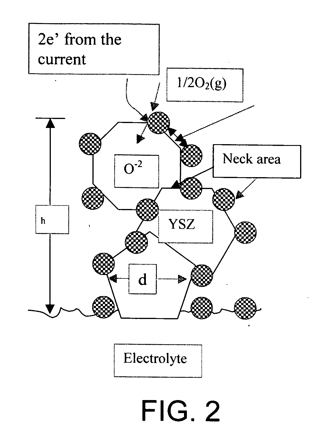
[0033] In a conventionally fabricated cathode, the neck size, α, can often be very small, thus increasing the cathode ionic resistivity and the cathode polarization resistance. In the present invention, the neck size is relatively large by the processing technique developed, whereupon first a complete sintering of a two-phase mixture is achieved, one phase being the ionic conductor and the other phase being a fugitive constituent. This facilitates full neck development. Thereafter, the fugitive constituent is removed, leaving behind a porous network of the ionic conductor with large neck sizes, and thus ensuring low effective ionic resistivity, ρeff. The final step consists of infiltrating the electronic conductor via, for example, an aqueous salt solution approach. It is believed that through the present method, neck development over the full range of α values can be achieved, usually greater than 0.1, and up to 0.7 and above.

Problems solved by technology

The performance of electrolyte-supported cells is limited by the large ohmic losses due to the thick electrolyte, while that of cathode-supported cells is limited by the large overpotentials at the supporting cathode electrode.
Although reasonably successful, there are some limitations to this method of fabrication.
First, the amount of porosity may not be adequate due to the partial sintering that occurs at temperatures above 1000° C., particularly at or above 1 150° C. Even with the addition of pore formers, the porosity may not be continuous (open) or have the desired morphology for optimal gas flow.
Thirdly, chemical reactions can occur between the solid electrolyte and the electrocatalyst at these high sintering temperatures resulting in the formation of undesired and often highly insulating phases.
Firing the composite powder for the sintering at a lower temperature may mitigate the problems of loss of porosity, decrease of TPB length, and undesirable chemical reactions, but if the temperature is too low the electrolyte phase will be poorly sintered with poor interparticle contact or necking between the particles.
A small neck size from inadequate sintering indicates poor interparticle contact and results in an increase in polarization.
However, the problem encountered in prior-art systems when the sintering temperature is so increased is a loss of porosity, and / or increased reactions leading to unwanted phases.
But, the potential of the electrode is not met because the sintering step required to form the porous surface with sufficient interparticle contact tends to also densify and collapse the porous structure left from the carbon removal.
The result is loss of the potential porosity in the structure.

Method used


Image

  • Method of fabricating composite cathodes for solid oxide fuel cells by infiltration
  • Method of fabricating composite cathodes for solid oxide fuel cells by infiltration
  • Method of fabricating composite cathodes for solid oxide fuel cells by infiltration

Examples


example

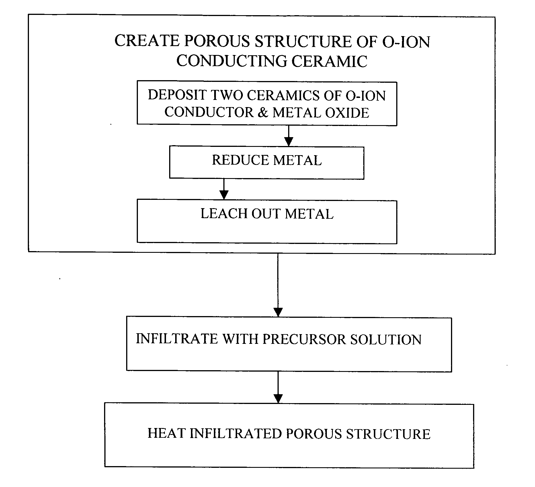
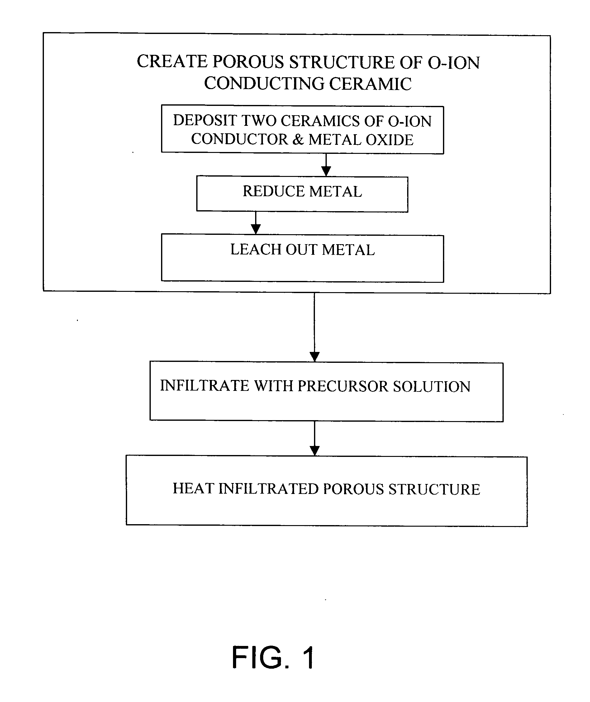
[0082] This example illustrates an embodiment of the present invention. In this example, a two-phase ceramic consisting of NiO and YSZ is deposited on the surface of the electrolyte where the cathode is intended, by applying a NiO and YSZ mixture and sintering. While the sintering temperature, about 1400° C., is high, the presence of the two phases inhibits grain growth and thus prevents over-coarsening of the microstructure.

[0083] The NiO—YSZ ceramic is exposed to a hydrogen environment at high temperature in order to reduce the NiO and thus form a Ni—YSZ cermet. The Ni is subsequently leached out with a dilute acid leaving behind a highly porous YSZ structure. The porous structure is then infiltrated with a solution containing La, Sr, and Mn nitrates and fired at low temperatures (500-800° C.) to form LSM. The result is a porous composite cathode consisting of LSM and YSZ. Alternatively, the porous YSZ structure can be fabricated by depositing a layer of YSZ containing a pore for...


PUM

PropertyMeasurementUnit
temperatureaaaaaaaaaa
temperaturesaaaaaaaaaa

Abstract

In the manufacture of a composite cathode, a porous structure is made of the electrolyte material by sintering a mixed material of primary material of the electrolyte and a secondary material. The mixture is treated to sinter the primary material. The secondary material is removed. The secondary material during sintering inhibits porosity loss and grain growth in the primary material while enabling formation of good necks for interparticle contact. The porous structure is then infiltrated with a liquid that contains precursors of an electrocatalytically active material. The infiltrated structure is then heated to convert the precursors to an electrocatalytically active material.

Description

CROSS REFERENCE TO RELATED APPLICATIONS [0001] (Not applicable) FEDERAL RESEARCH STATEMENT [0002] (Not applicable) BACKGROUND OF INVENTION [0003] The three standard designs of solid oxide fuel cells (SOFC) are electrolyte-supported, cathode-supported, and anode-supported. The performance of electrolyte-supported cells is limited by the large ohmic losses due to the thick electrolyte, while that of cathode-supported cells is limited by the large overpotentials at the supporting cathode electrode. It has been shown that the performance of anode-supported cells is superior to that of electrolyte and cathode-supported cells due to the reduced thickness of the electrolyte and cathode, as well as the low overpotentials exhibited by the anode support. Even so, in such cells the largest contribution to overpotential losses is from the cathode while the ohmic losses from the electrolyte and overpotential losses at the anode are considerably smaller. [0004] The two main contributors to the po...

Claims


Application Information

Patent Timeline
Patent Type & Authority Applications(United States)
IPC IPC(8): B05D3/02B05D5/12H01M4/86H01M4/88H01M8/12
CPCH01M4/8885H01M4/9033H01M4/9066Y02E60/50H01M2004/8689H01M2008/1293Y02E60/525H01M8/1253Y02P70/50
Inventor ARMSTONG, TAD JOHNVIRKAR, ANIL VASUDEO
Owner VERSA POWER SYST
Learn More