
Reactive metal sources and deposition method for thioaluminate phosphors

a thioaluminate and phosphor technology, applied in the field of phosphor deposition, can solve the problems of loss of luminance and energy efficiency, difficult control of stoichiometry of phosphor films, and relatively poor luminosity and stability, so as to improve the luminance and emission spectrum, reduce the degree of control, and achieve high, yet uniform luminosity

Inactive Publication Date: 2005-09-15
IFIRE IP CORP
View PDF17 Cites 12 Cited by
  • Summary
  • Abstract
  • Description
  • Claims
  • Application Information

AI Technical Summary

Benefits of technology

"The present patent relates to a method for depositing thioaluminate phosphor compositions, particularly for full-color electroluminescent displays. The method improves the purity and luminance of the phosphor materials, allowing for the deposition of large area thin films with high luminosity and suitable emission color. The method involves providing source materials and an activator species, and effecting deposition in a sulfur-bearing vapor atmosphere. The technical effects include improved purity and luminance of the phosphor materials, as well as a more uniform and high-quality deposition of the phosphor composition."

Problems solved by technology

However, the optical emission from this phosphor material must be passed through an appropriate chromatic filter to achieve the necessary colour co-ordinates for blue sub-pixels, resulting in a loss of luminance and energy efficiency.
These compounds provide good blue colour co-ordinates, but have relatively poor luminosity and stability.
Since the host materials are ternary compounds, it is relatively difficult to control the stoichiometry of the phosphor films.
Europium activated barium thioaluminates provide excellent blue colour co-ordinates and higher luminance, but as a ternary compound, its stoichiometry is also somewhat difficult to control.
Vacuum deposition of barium thioaluminate phosphor films comprising this material from a single sulfide source pellet using sputtering or electron beam evaporation has not yielded films with adequately high luminosity.
However, this technique is not readily scalable to facilitate commercial production of large area displays and the process cannot be adequately controlled to compensate for changes in the evaporation rates from the two sources as the deposition proceeds and the source pellets are depleted.
Furthermore, the required relative evaporation rates must be calibrated for each specific piece of deposition equipment and the requirement for multiple sources constrains the design of the deposition equipment, which generally adds to the cost of the equipment.
Lastly, certain known evaporation methods are not well suited for the deposition of large area films such as a required for the fabrication of large electronic displays such as those for the wall television application.
However, this method does not fully solve the problem of providing a stable phosphor film during display operation and at the same time providing a method that can be used for the economic deposition of phosphor films over large areas.
In this method, however, the composition modulation across the thickness of the deposited layer is problematical for subsequent reaction of the deposited materials to form a homogeneous single phase phosphor material, since atomic species are required to diffuse within the deposited film to achieve a homogeneous composition on an atomic scale.

Method used


Image

  • Reactive metal sources and deposition method for thioaluminate phosphors
  • Reactive metal sources and deposition method for thioaluminate phosphors
  • Reactive metal sources and deposition method for thioaluminate phosphors

Examples


example 1

[0045] A cylindrical barium aluminum sputtering target of diameter 7.6 cm and thickness of 6 mm with a composition of 47.5 atomic percent barium, 47.5 atomic percent aluminum and 5 atomic percent europium was prepared (ACl Alloys of San Jose, Calif.). The target was used in an Edwards model FL400 rf magnetron sputtering system as the sole source of barium, aluminum and europium to reactively sputter a europium doped thioaluminate film under a gas pressure of 0.2 to 0.5 Pascals.

[0046] Several electroluminescent devices were fabricated with phosphor films deposited using the sputtering system described above. The sputtering process gas was an argon hydrogen sulfide mixture introduced into the sputtering chamber during film deposition with the ratio of argon to hydrogen sulfide in the gas mixture ranging from 1:1 to 4:1. The rf power applied to the sputtering target for the depositions was 200 watts.

[0047] The deposition substrates were 5 cm by 5 cm glass substrates similar to those ...

example 2

[0050] Electroluminescent devices similar to those of example 1 were prepared, except that the target composition for phosphor deposition was 17 atomic percent barium, 81 atomic percent aluminum and 2 atomic percent europium. These devices did exhibit electroluminescence under the test conditions of example 1. The concentration of elements in the deposited phosphor films as measured by energy dispersive x-ray analysis (EDX) on films deposited on silicon wafers placed immediately adjacent to the EL device substrates as a function of the ratio of argon to hydrogen sulfide in the process gas for phosphor sputtering is shown in FIG. 2. A complete chemical analysis of the phosphor films, also measured using EDX on films deposited on silicon wafers, is shown for several devices incorporating thick film dielectric layers in Table 1. Table 1 also shows threshold voltage and the luminance and the CIE y colour co-ordinates of the devices measured at 60 volts above the threshold voltage, measu...

example 3

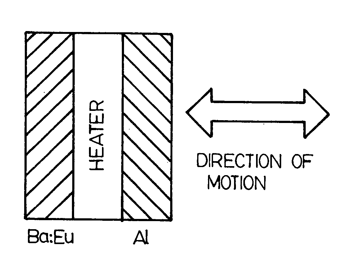
[0052] An electroluminescent device similar to that of example 1 was prepared, except that it had a 50 nm thick layer of barium tantalate between the thick film dielectric layer and the phosphor layer. Furthermore, the phosphor was deposited by thermal evaporation in a Dynavac box coater using a thermal source for barium and europium consisting of pellets of metallic barium of approximate dimension 2 to 5 mm that were alloyed with 6 atomic percent of europium and a second thermal source pellet consisting of pieces of aluminum sulfide of approximate dimension 2 to 10 mm. Prior to deposition, the deposition chamber was pumped down to a base pressure of 7×10⁻³ Pa. Supplementary sulfur was provided in the deposition chamber by the injection of hydrogen sulfide at a rate of 150 sccm to maintain a working pressure of 3×10⁻² Pa during the deposition process. The barium source pellet was heated to melt these source materials.

[0053] The deposition chamber was fitted with a nitrogen cold tra...


PUM

PropertyMeasurementUnit
humidityaaaaaaaaaa
thicknessaaaaaaaaaa
rf poweraaaaaaaaaa

Abstract

A physical vapour deposition method for the deposition of thioaluminate phosphor compositions includes providing one or more source materials including an intermetallic barium aluminum compound, a barium aluminum alloy or a protected barium metal, providing an activator species and effecting deposition of the one or more source materials and activator species as a phosphor composition on a selected substrate. The method allows for the deposition of blue thin film electroluminescent phosphors with high luminance and colors required for TV applications.

Description

CROSS REFERENCE TO RELATED APPLICATIONS [0001] This application claims the benefit of the filing date of U.S. Provisional Patent Application No. 60 / 549,552, filed Mar. 4, 2004.BACKGROUND [0002] The present embodiments relate to the deposition of phosphor materials in full colour ac thick film dielectric electroluminescent displays. More specifically, they are directed to a novel physical vapour deposition method for depositing thioaluminate thin film phosphor compositions using one or more source materials that comprise barium. [0003] Thick film dielectric structures as described in U.S. Pat. No. 5,432,015 (the disclosure of which is incorporated herein by reference in its entirety) provide superior resistance to dielectric breakdown as well as a reduced operating voltage as compared to thin film electroluminescent (TFEL) displays. The thick film dielectric structure as deposited on a ceramic substrate will withstand somewhat higher processing temperatures than TFEL devices, which a...

Claims


Application Information

Patent Timeline
Patent Type & Authority Applications(United States)
IPC IPC(8): C09K11/70C23C14/06C23C14/34C23C16/00
CPCC23C14/0057H05B33/145C23C14/3414C23C14/0623C22C21/00
Inventor KOSYACHKOV, ALEXANDERLIU, GUOWU, XINGWEIACCHIONE, JOE
Owner IFIRE IP CORP
Learn More