Magnetic coupler for holding a magnetic pumping or mixing element in a vessel
a technology of magnetic pumping or mixing element and magnetic coupler, which is applied in the field of magnetic coupler, can solve the problems of significant deleterious effect on sensitive fluids, and achieve the effects of enhancing the magnetic stiffness and loading capacity of the bearing, reducing separation distance, and minimizing thermal transfer
- Summary
- Abstract
- Description
- Claims
- Application Information
AI Technical Summary
Benefits of technology
Problems solved by technology
Method used
Image
Examples
first embodiment
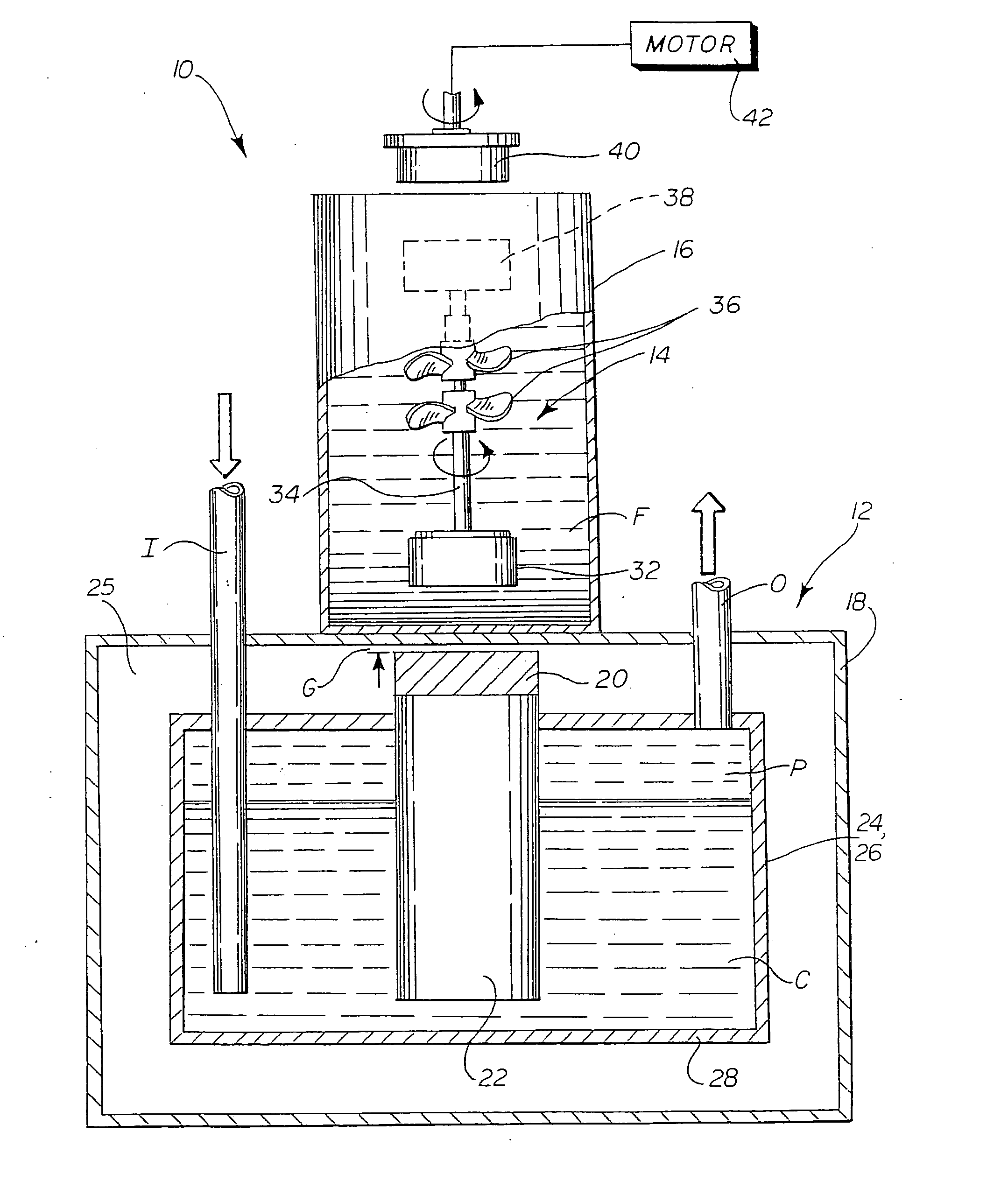
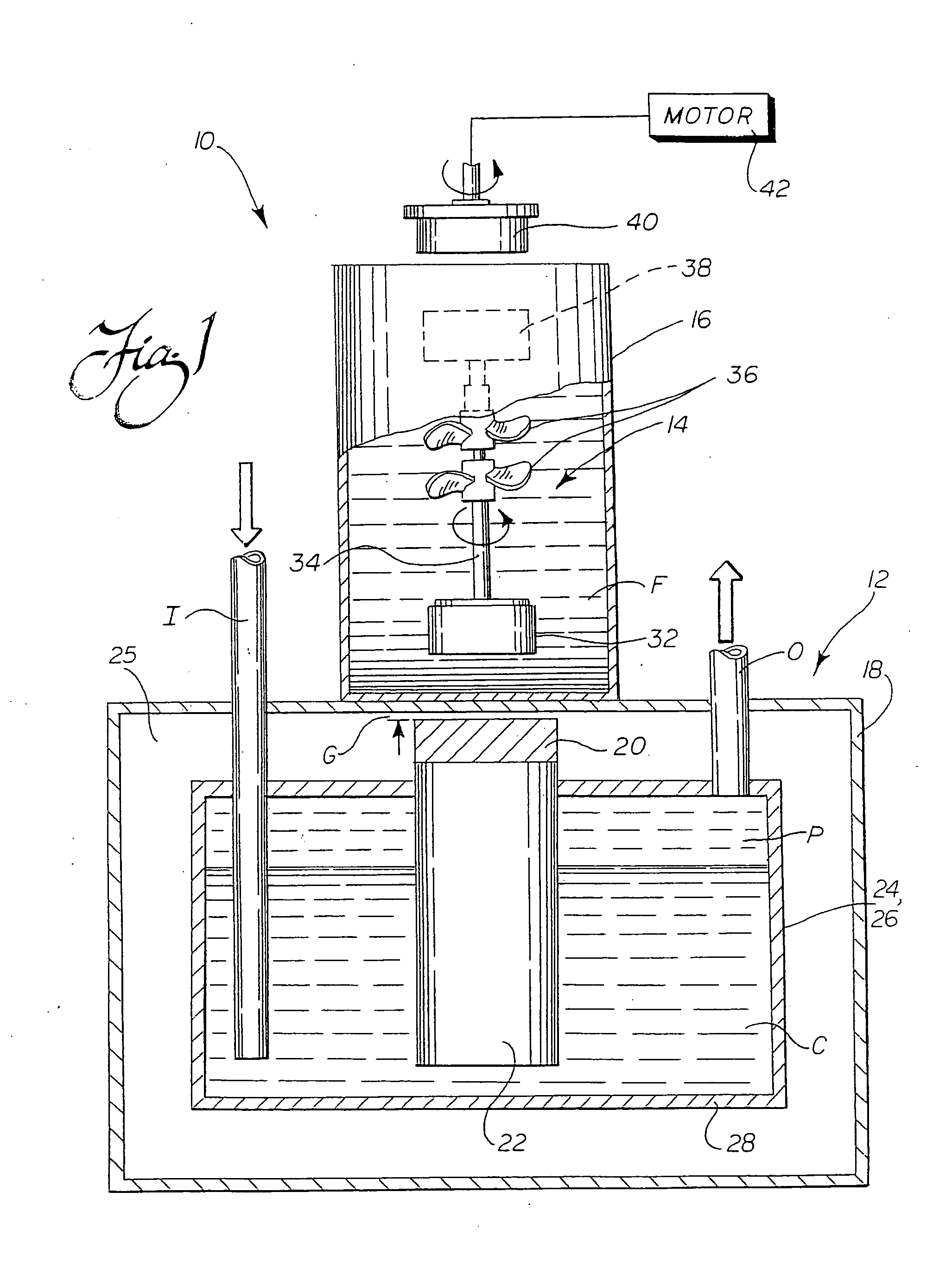
[0080] As should be appreciated from viewing FIG. 1, and as briefly noted in the foregoing description, the combination of the outer wall 18 and the inner cooling chamber 26 in this first embodiment defines the chamber 25 around the superconducting element 20. Preferably, this chamber 25 is evacuated to minimize heat transfer from the cooling chamber walls 28 and the superconducting element 20 to the outer wall 18 of the cryostat 12. The evacuation pressure is preferably at least 10−3 torr, and most preferably on the order of 10−5 torr, but of course may vary depending upon the requirements of a particular application. The important factor is that thermal transfer from the cooling source 24, which in this case is the cooling chamber 26 holding a cryogen C, and the superconducting element 20 to the outer wall 18 is minimized to avoid cooling the vessel 16 or fluid F held therein. Although a vacuum chamber 25 is proposed as one preferred manner of minimizing this thermal transfer, the...
second embodiment
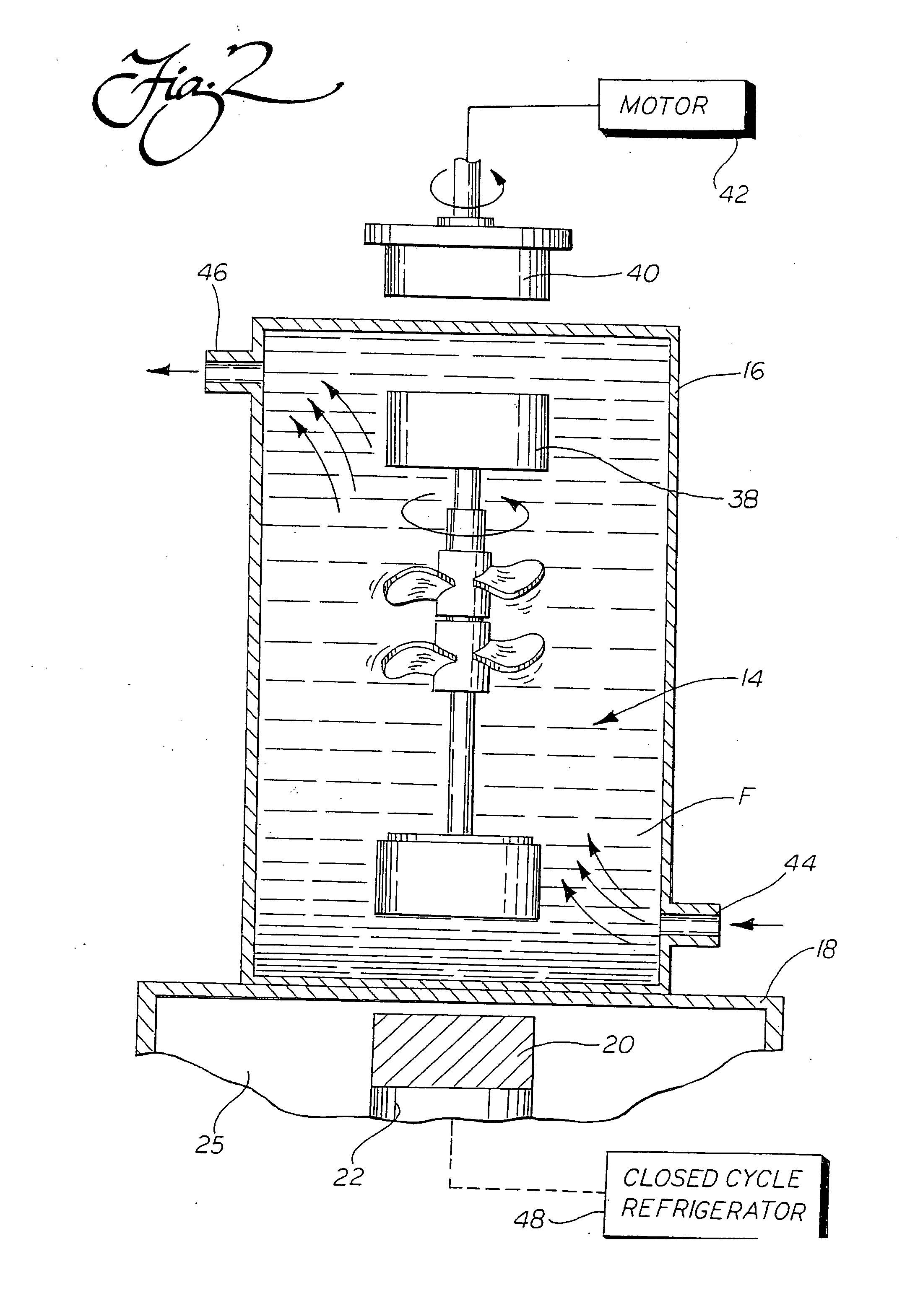
[0089] In accordance with another of the many important aspects of the present system 10, the absence of a mixing rod or other mechanical stirrer extending through a wall of the vessel 16 also allows for placement of the magnetic bearing 14 at an off-axis position, as shown in FIG. 3. Specifically, the superconducting element 20, magnetic bearing 14, and drive magnet 40 are all axially aligned away from the vertical center axis of the vessel 16. One particular advantage of using this approach is that the magnetic bearing 14 may be rotated at a very low speed while the vessel 16 is also rotated about its center axis. This advantageously ensures that gentle, yet thorough mixing, is achieved, which is particularly advantageous for use with fluids that are sensitive to shear stress. As should be appreciated, this arrangement can be used both whether the vessel 16 is completely sealed, provided with an inlet 44 and an outlet 46 for pumping as shown in FIG. 2, or open to the ambient envir...
third embodiment
[0112] In accordance with yet another aspect of the present invention, 5 a third version of a pumping or mixing system 200 is disclosed. In this third embodiment, which is illustrated in FIGS. 9, 9a, 9b, and 10, the forces for driving and levitating the magnetic bearing 204 are supplied from the same side of a fluid vessel 202 (which is shown as an open-top container, but as described above, could be a sealed container, a pumping chamber or head, a flexible bag, a pipe, or the like). In this system 200, the magnetic bearing 204 actually includes two magnetic subsystems: a first one that serves to levitate the magnetic bearing 204, which includes a first magnet 206, preferably in the form of a ring, and a second magnetic subsystem that includes at least two alternating polarity driven magnets 208a, 208b, preferably positioned inside of the first, ring-shaped magnet 206, to transmit driving torque to the bearing (see FIGS. 9a and 9b).
[0113]FIG. 9 shows one embodiment of the overall sy...
PUM
 Abstract
Description
Claims
Application Information
 - R&D
- Intellectual Property
- Life Sciences
- Materials
- Tech Scout
- Unparalleled Data Quality
- Higher Quality Content
- 60% Fewer Hallucinations
Browse by: Latest US Patents, China's latest patents, Technical Efficacy Thesaurus, Application Domain, Technology Topic, Popular Technical Reports.
© 2025 PatSnap. All rights reserved.Legal|Privacy policy|Modern Slavery Act Transparency Statement|Sitemap|About US| Contact US: help@patsnap.com


