
Gas-liquid separation method and unit

a gas-liquid separation and gas-liquid technology, applied in the direction of liquid degasification, separation process, dispersed particle separation, etc., can solve the problems of complex apparatus, inability to apply to degassing for a byproduct gas generated by a reaction, and inability to exist, so as to achieve convenient monodispersibility, small particle size, and constant quality

Inactive Publication Date: 2005-05-26
FUJIFILM CORP +1
View PDF7 Cites 22 Cited by
  • Summary
  • Abstract
  • Description
  • Claims
  • Application Information

AI Technical Summary

Benefits of technology

[0013] In such a background, a gas-liquid separation method and unit is required, which removes a byproduct gas evolving along with a reaction without destabilizing the flow of a reaction liquid. Such a gas-liquid separation unit for satisfying the requirement is extremely useful, because of enabling continuous production of the above described metal microparticle as well as improving the particle sizes and the monodispersibility of the produced metal microparticles.
[0030] If metal microparticles are contained in a magnetic layer of a magnetic recording medium, the method and the unit can consequently improve the quality of the magnetic recording medium.

Problems solved by technology

However, there is a problem that such a film material as to satisfy them does not exist.
Accordingly, the degassing method with the separating film has no problem in the case of treating a gas and a liquid having low reactivity such as in degassing of dissolved oxygen in water, but can not be applied to degassing for a byproduct gas generated by a reaction.
A degassing method utilizing adsorption has many restrictions in chemical resistance and solvent resistance of an adsorbent, as in the case of a separating film, and has a further problem that, in order to speed up the adsorption, incidental facilities such as a compression device are necessary, which make the apparatus complicated.
A degassing method using decompression can remove gas through a decompressing operation, but when a raw material, a solvent and a reaction product are volatile, the degassing method can not be used, because they also volatilize by decompression.
When the method is still used, the method needs an operation of separating the raw material, the solvent and the reaction product which have volatilized together with the gas, in a later step of degassing treatment, and thus causes a problem of making the apparatus complicated.
However, when a raw material, a solvent and a reaction product are volatile, there is a problem that these also volatilize together with the gas by heat.

Method used


Image

  • Gas-liquid separation method and unit
  • Gas-liquid separation method and unit
  • Gas-liquid separation method and unit

Examples


embodiment 1

[0119] In a nitrogen gas of high purity, the operation described below is carried out.

[0120] Into the aqueous solution of a reducing agent having 0.50 g of NaBH4 (made by Wako Pure Chemical Industries, Ltd.) dissolved in 16 ml of H2O (previously deoxygenated into 0.1 mg / l or less of dissolved oxygen), an alkane solution having aerosol 10.8 g of OT (made by Wako Pure Chemical Industries, Ltd.) mixed with 80 ml of decane (made by Wako Pure Chemical Industries, Ltd.) and 2 ml of oleylamine (made by Tokyo Kasei Kogyo Co., Ltd.) was added and mixed to prepare a reversed micelle solution which is a first solution L1.

[0121] Into a metal salt aqueous solution containing 60 g of iron(III) triammonium trioxalate trihydrate (Fe(NH4)3(C2O4)3) (made by Wako Pure Chemical Industries, Ltd.) and 0.50 g of potassium chloroplatinate (K2PtCl4) (made by Wako Pure Chemical Industries, Ltd.) dissolved in 8 ml of H2O (previously deoxygenated into 0.1 mg / l or less of dissolved oxygen), an alkane solution...

embodiment 2

[0128] Except that the amount of H2O (previously deoxygenated into 0.1 mg / l or less of dissolved oxygen) in a first solution L1 of a reversed micelle solution was made to be 40 ml and the amount of H2O (previously deoxygenated into 0.1 mg / l or less of dissolved oxygen) in the second solution L2 of a reversed micelle solution was made to be 20 ml, the same operation was conducted as in the embodiment 1, to obtain a dispersion containing metal nanoparticles of FePt dispersed in a liquid having a mass ratio (water / surface active agent) of water to a surface active agent in the value of 5.

[0129] The metal nanoparticles obtained by a conventional method and a method according to the present invention were subjected to the same measurement as in the embodiment 1, of the yield, the composition, the volume, the average particle diameter and particle size distribution (coefficient of variation), and the coercive force. These measuring methods are the same methods as used in the embodiment 1...

embodiment 3

[0132] Except that the amount of H2O (previously deoxygenated into 0.1 mg / l or less of dissolved oxygen) in the first solution L1 of a reversed micelle solution was made to be 64 ml and the amount of H2O (previously deoxygenated into 0.1 mg / l or less of dissolved oxygen) in the second solution L2 of a reversed micelle solution was made to be 32 ml, the same operation was conducted as in the embodiment 1, to obtain a dispersion containing metal nanoparticles of FePt dispersed in a liquid having a mass ratio (water / surface active agent) of water to a surface active agent in the value of 8.

[0133] The metal nanoparticles obtained by a conventional method and a method according to the present invention were subjected to the same measurement as in the embodiment 1, of the yield, the composition, the volume, the average particle diameter and particle size distribution (coefficient of variation), and the coercive force. These measuring methods are the same methods as used in the embodiment...


PUM

PropertyMeasurementUnit
Timeaaaaaaaaaa
Pressureaaaaaaaaaa
Volumeaaaaaaaaaa

Abstract

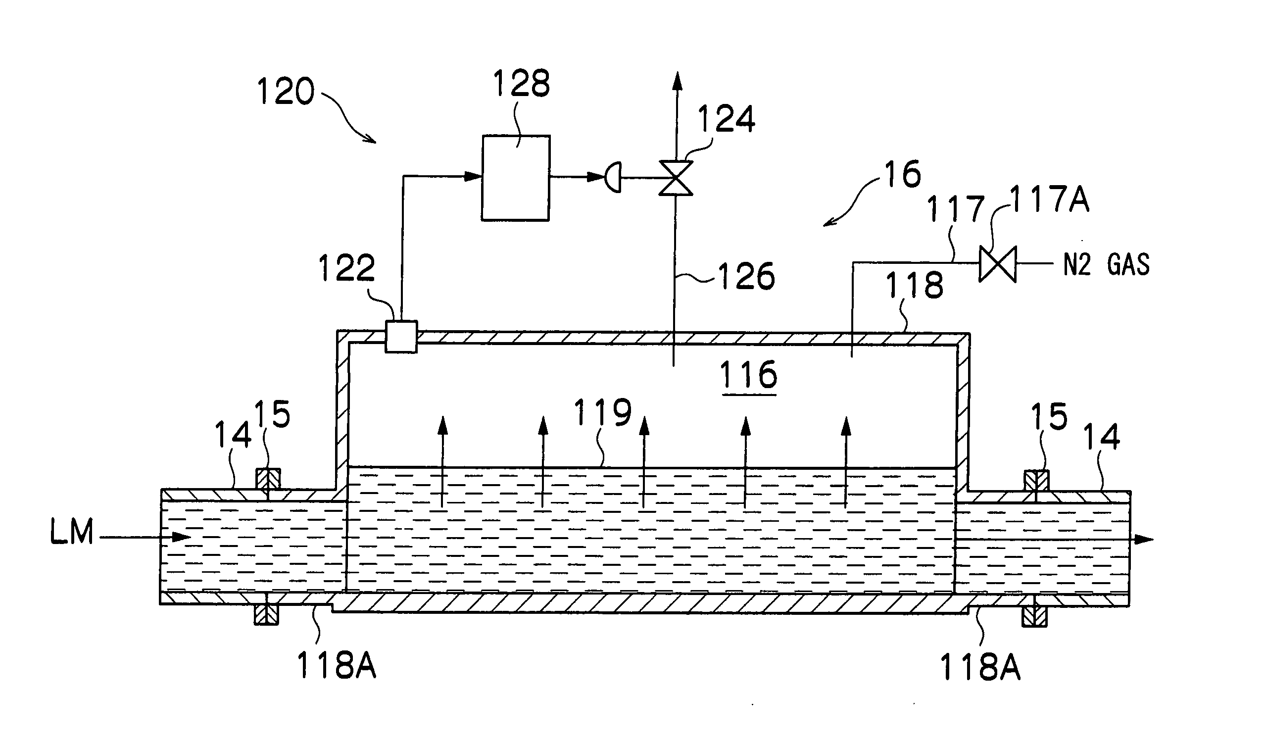
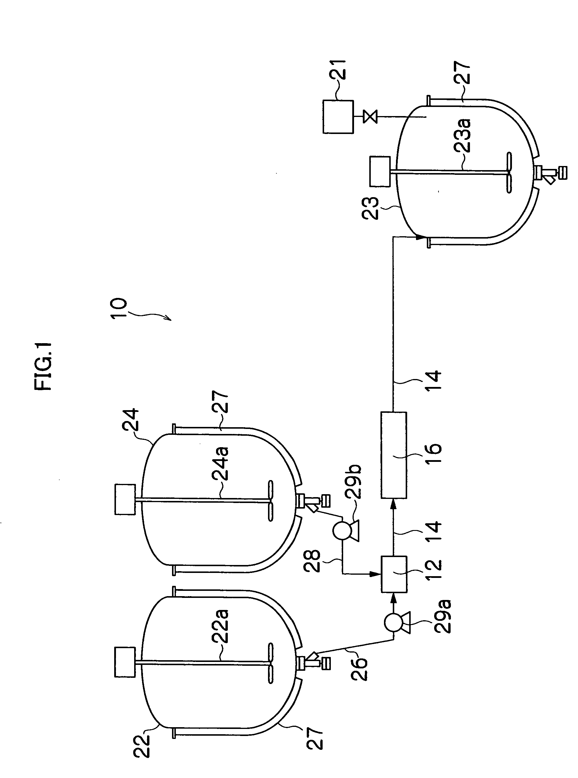
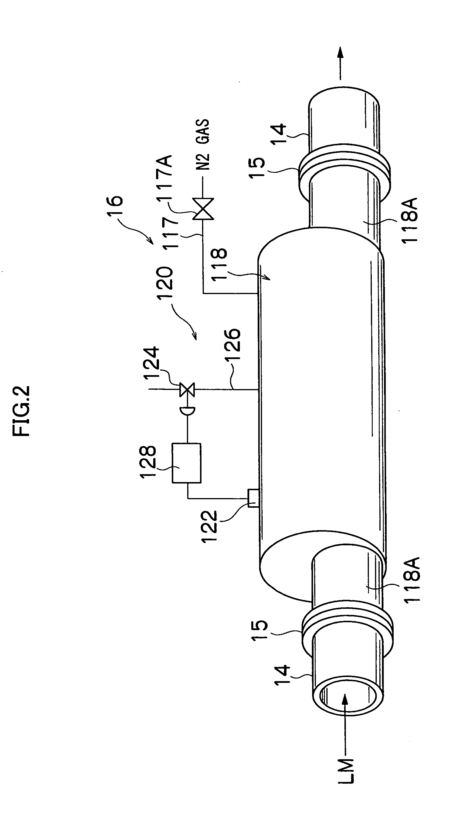
When a reaction liquid is passed through a gas-liquid separation pipe having a larger volume per unit length than the volume per unit length of a pipe, a headspace part into which gas can be released is formed above the gas-liquid separation pipe, and the byproduct gas generated by the reaction changes into bubbles, moves upward in the reaction liquid, and is continuously released from a gas-liquid interface into the headspace part. While the gas is removed in the gas-liquid separation pipe, the pressure of the headspace part is controlled so as to be constant by a pressure adjustment device.

Description

BACKGROUND OF THE INVENTION [0001] 1. Field of the Invention [0002] The present invention relates to a gas-liquid separation method and unit, and particularly relates to a gas-liquid separation method and unit suitable for removing a byproduct gas generated in a reaction for forming metal microparticles with a continuous production process of the metal microparticles. [0003] 2. Description of the Related Art [0004] Magnetic particles contained in a magnetic layer constituting a magnetic recording medium have preferably small particle sizes and superior monodispersibility from the viewpoint of the quality. In producing the metal microparticles, a reaction for forming the metal microparticles is occasionally accompanied by the generation of a byproduct gas (for instance, hydrogen gas). [0005] The reaction accompanied by the byproduct gas is so hardly continued that a continuous processing apparatus for continuously producing the above described metal microparticles has not yet practic...

Claims


Application Information

Patent Timeline
IPC IPC(8): B01D19/00B22F9/24
CPCB01D19/0042B01D19/0036
Inventor SHIRAISHI, FUMIKOICHIKAWA, YASUNORISUGIYAMA, SEIJIWAKI, KOUKICHI
Owner FUJIFILM CORP
Learn More