
Electrical interconnect for a fuel cell stack

Inactive Publication Date: 2005-05-19
ESTCO BATTERY MANAGEMENT
View PDF8 Cites 9 Cited by
  • Summary
  • Abstract
  • Description
  • Claims
  • Application Information

AI Technical Summary

Benefits of technology

[0016] It is an object of the present invention to obviate or mitigate at least one disadvantage of previous electrical interconnects.
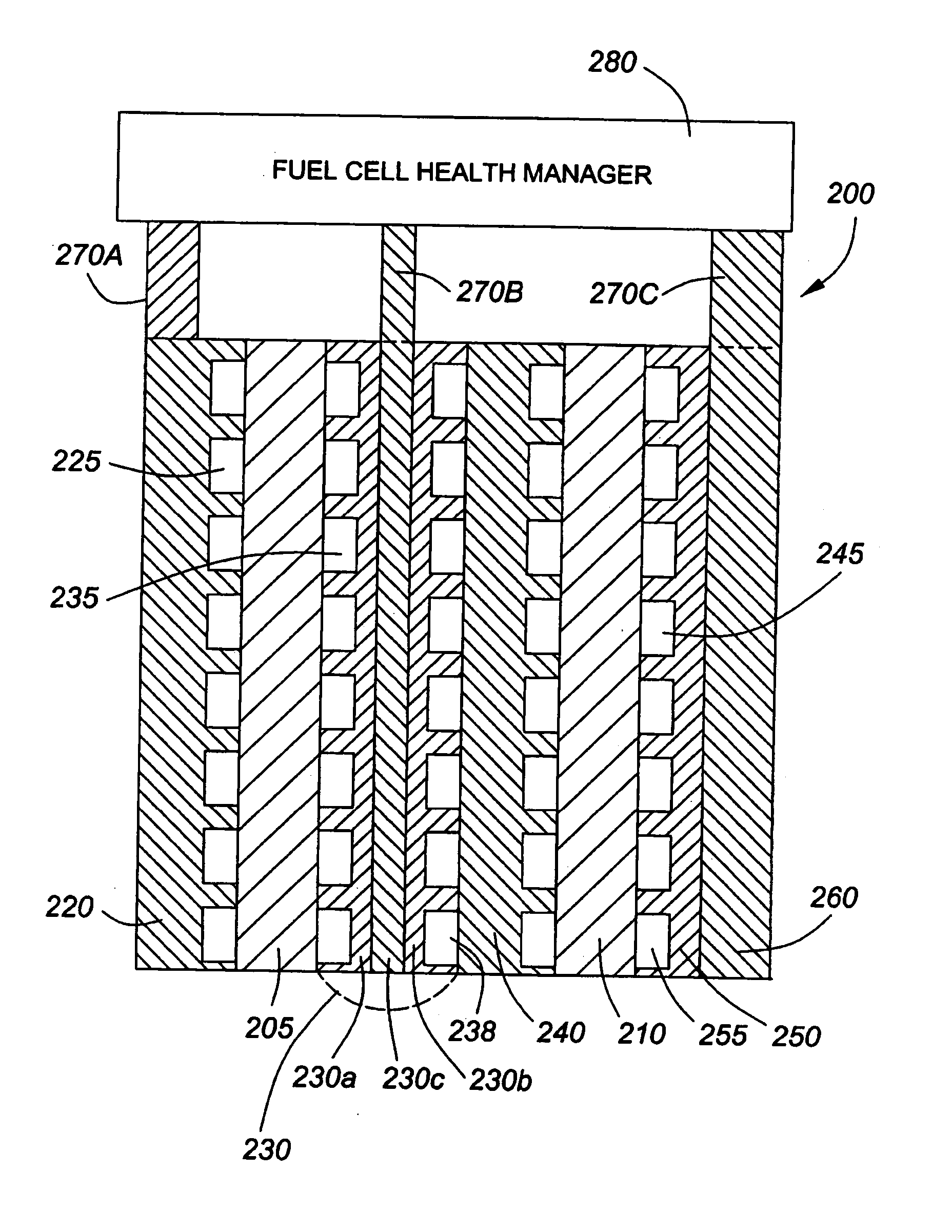
[0017] The present invention provides an electrical interconnect for use in a fuel cell stack. The present invention further provides a fuel cell assembly, for use in the electrochemically active section of a fuel cell stack, comprising one or more membrane electrode assemblies (MEA), each disposed between two flow field plates that distribute fuel and oxidant to the anode and the cathode, an additional flow field plate for passing coolant in order to cool the assembly and, possibly, a buss plate. At least one of these plates is an electrical interconnect of the present invention. According to the present invention, the electrical interconnect is constructed to include one or more electrically conductive tabs, where one or more of the tabs are in turn coupled to a Fuel Cell Health Manager (FCHM). The FCHM is able to monitor, control, rejuvenate, supplement, and bypass the fuel cell assembly through the connection made via the tabs.
[0021] The interconnects are made from a highly electrically conductive material such that the voltage drop across each plate member provided by an FCHM is small, thus allowing the current density across the MEA to be essentially uniform. The material of each interconnect is advantageously selected based on its electrical and thermal conductivities and its chemical stability in the operating environment of the fuel cell. A significant benefit of the present invention is that the inventive interconnect creates a more uniform voltage over the plate area due to enhanced conductivity. This, in turn, improves fuel cell stack performance and life.
[0025] In a fourth aspect, the present invention provides a fuel cell assembly for use in a fuel cell stack with an FCHM or similar device, the fuel cell assembly comprising: at least one membrane electrode assembly (MIA), each of the at least one MEA having an electrolyte membrane disposed between an anode and a cathode respectively; a first flow field plate being disposed along a first side of the fuel cell; a second flow field being disposed along a second side of the fuel cell; a plate member being made of highly electrically conductive material such that the voltage drop across each plate member, provided by the FCHM, provides for a uniform current density across the MEA, the plate member being of suitable thermal conductivity and chemical stability for use with the at least one MEA, and the plate member being disposed along the second flow field plate; and a tab being made of electrically conductive material, for electrically connecting the plate to the FCHM.

Problems solved by technology

The current art of connecting a plurality of individual fuel cells in series to achieve higher voltages leads to the disadvantage that all of the connected fuel cells can be rendered inoperable if one of the fuel cells in the fuel cell stack fails.
These impure hydrogen streams commonly contain significant amounts of electrocatalyst poisons such as carbon monoxide, which seriously degrade the power output of the fuel cell stack.
The existing fuel cell plate designs have electrical and / or physical deficiencies that make connection of the Fuel Cell Health Manager (FCHM) systems disclosed in U.S. Pat. No. 6,339,313 and U.S. Pat. No. 6,541,941, difficult or impossible.
With typical electrode currents in PEM fuel cell stacks being of the order of 1 A / cm2, it can easily be shown that unacceptably large voltage drops (several hundreds of mV) will occur when currents are introduced into the edge of the plates in high power stacks.
Such large voltage drops will result in uneven distribution of current through the plates and ineffective removal of fuel cell poisons.
Existing fuel cell plates also fail to provide the extensions that are needed for electrical connection of the FCHM to the stack and for heat removal from high power FCHM electronic components such as Metal Oxide Field Effect Transistors (MOSFETs).

Method used


Image

  • Electrical interconnect for a fuel cell stack
  • Electrical interconnect for a fuel cell stack
  • Electrical interconnect for a fuel cell stack

Examples


second embodiment

[0038]FIG. 4 illustrates a sectional view of a group of fuel cell assemblies 200 according to the present invention. The group 200 includes two fuel cells 205, 210, disposed between flow field plates 220, 230, 240, 250, where particular flow field plates also form electrical interconnects 220, 230, in accordance with the present invention and where a further electrical interconnect 260 of the present invention is also included. The flow field plates 220, 230, 240, 250 each provide one or more layers of flow field channels 225, 230, 235, 238, 245, 255, respectively. The first flow field plate 220 provides a set of flow field channels 225. This set of flow field channels 225 may either stream fuel or oxidant to the first fuel cell 205 depending on whether the first flow field plate 220 is disposed along the anode or cathode side of the first fuel cell 205. The second flow field plate 230 is constructed to provide two flow field channels 235, 238, where a first set of flow field channe...

third embodiment

[0042]FIG. 5 illustrates a sectional view of an electrical interconnect 300 according to the present invention. The electrical interconnect 300 is similar the electrical interconnect 230 of FIG. 4 where the electrical interconnect 300 could be arranged in a group of fuel cell assemblies as is electrical interconnect 230 in FIG. 4. In FIG. 5, this sectional view shows an oxidant flow field 320 on the oxidant distribution side of the plate 310. The oxidant flow field 320 is formed in the surface of the plate to allow for distribution of oxidant to the cathode and for removal of product water produced by the operation of the particular fuel cell. The serpentine flow pattern of the oxidant flow field 320 is known in the prior art and will not be further elaborated upon in this document.

[0043] The electrical interconnect 300 is made from a highly electrically conductive material such that the voltage drop across each plate member, provided by the current from an FCHM, is small. In additi...


PUM


Abstract

A plate, an electrical interconnect formed by the plate, and a fuel cell assembly incorporating the electrical interconnect. The electrical interconnect is for use in a fuel cell stack. The fuel cell assembly is for use in the electrochemically active section of a fuel cell stack. The assembly includes one or more membrane electrode assemblies (MEA), each disposed between two flow field plates that distribute fuel and oxidant to the anode and the cathode, an additional flow field plate for passing coolant in order to cool the assembly and, possibly, a buss plate. At least one of the buss plates is an electrical interconnect of the present invention. The electrical interconnect is constructed to include one or more electrically conductive tabs, where one or more of the tabs are in turn coupled to a fuel cell health management (FCHM) device that is able to monitor, control, rejuvenate, supplement, and bypass the fuel cell assembly through the connection made via the tabs. The tabs may also be utilized as mounts and heat sinks for high power electronic components associated with the FCHM, the heat generated by these FCHM components being dissipated by the fuel cell stack cooling system. The plate members are made from a highly electrically conductive material such that the voltage drop across each plate member provided by an FCHM is small thus allowing the current density across the MEA to be essentially uniform since the voltage throughout the area of the plate is more uniform that in the usual plate design. The material of the plate member is advantageously selected based on its electrical and thermal conductivities and its chemical stability in the operating environment of the fuel cell.

Description

RELATED APPLICATIONS [0001] The present invention claims priority from U.S. Provisional Patent Application Ser. No. 60 / 512,782 filed 21 OCT. 2003 and herein incorporates such document by reference.FIELD OF THE INVENTION [0002] The present invention relates generally to the electrical connection between fuel cell health management and control systems and fuel cell stacks. More particularly, the present invention relates to an electrical interconnect for use with fuel cell stacks for example polymer electrolyte membrane (PEM) fuel cell stacks. BACKGROUND OF THE INVENTION [0003] A fuel cell is an energy conversion device that electrochemically reacts a fuel with an oxidant to generate direct current (DC) power. A fuel cell typically consists of an anode, an electrolyte material and a cathode. In a Polymer Electrolyte Membrane (PEM) fuel cell, the anode and the cathode are bonded onto the polymer electrolyte material to form an individual cell. The individual cell generates a relatively...

Claims


Application Information

Patent Timeline
IPC IPC(8): H01M8/02H01M8/04H01M50/528
CPCH01M8/0206H01M8/0228Y02E60/50H01M8/0267H01M2008/1095H01M8/0247H01M8/241H01M8/2483H01M8/0263H01M8/0258
Inventor ADAMS, WILLIAM A.GARDNER, CHRISTOPHER L.BLAIR, JAMES DONALDSON
Owner ESTCO BATTERY MANAGEMENT
Learn More