
Hydrogen purification process using pressure swing adsorption for fuel cell applications

a technology of hydrogen purification and pressure swing adsorption, which is applied in the direction of hydrogen separation using solid contact, separation process, products, etc., can solve the problems of affecting processor performance, carbon monoxide and water are produced, and the cost of meas is relatively high

Inactive Publication Date: 2005-05-12
GENERAL MOTORS COMPANY
View PDF35 Cites 56 Cited by
  • Summary
  • Abstract
  • Description
  • Claims
  • Application Information

AI Technical Summary

Problems solved by technology

MEAs are relatively expensive to manufacture and require certain conditions for effective operation.
However, carbon monoxide and water are also produced.
However, the use of a PROX reactor in a fuel processor affects processor performance.
Also, the PROX reactor is not 100% selective, and thus results in consumption of hydrogen.
Therefore, some hydrogen that would normally be available to provide power is consumed by the PROX reactor.
Further, the heat generated from the PROX reactor is at low temperature, resulting in excess low-grade heat.
Also, typical catalysts used in a PROX reactor contain precious metals, such as platinum or iridium, which are very expensive.
Thus, the reformate gas is not suitable for compression and storage because much energy would be wasted in compressing the non-hydrogen components in the reformate gas.
Also, valuable storage space would be wasted to contain the non-hydrogen components.
Typical membranes for these applications contain palladium, which is very expensive.
), and thus, it takes a long time after the low temperature start-up for a fuel processing system containing hydrogen permeable membranes to be able to generate hydrogen.
Additionally, these membranes operate at very high pressures (>5 bar), which leads to high compressor loads and inefficient systems.
Such a system cannot be used as a stand-alone hydrogen generator, where the hydrogen gas is stored for subsequent use in a fuel cell engine.
These PSA units, however, include complex valve arrangements and are non-continuous due to the cycling of these valves.
However, the PSA equipment and cycles of industrial hydrogen are not ideal for purifying hydrogen for fuel cell applications where autothermal reforming (ATR) or catalytic partial oxidation (CPO) of hydrocarbon fuel are used to generate the hydrogen.
Processes that require air compression for the ATR or CPO would be inefficient at these elevated pressures, and would preferably operate at pressures of five atmospheres or less.
Typical industrial hydrogen PSA units also operate at lower temperatures than those suited for integration with fuel cell systems, where it is not desirable to cool the hydrogen stream to ambient temperature only then to subsequently reheat the hydrogen to the fuel cell stack operating temperature of 60-100° C. Additionally, industrial hydrogen PSA units in steam reforming plants are designed to purify a stream that contains greater than 75% hydrogen, whereas, the product gas from an ATR typically contains no more than 50% hydrogen.
Cycles with large numbers of equalization steps are more efficient at higher pressure, but at lower pressures they add more complexity to the PSA process without providing a significant performance benefit.
While the use of a vacuum for purging the adsorbents enhances the hydrogen recovery, it has an additional parasitic power load to the PSA system in addition to the high air compression requirements.
However, these patents do not describe the design of a PSA unit with a specific PSA cycle that can accomplish the desired hydrogen purification.
However, these hydrogen PSA units are not designed for the desired relatively low pressures and low feed hydrogen concentrations that are seen in processes which use ATR or CPO for hydrogen generation, and thus, have very low hydrogen recoveries under these conditions.

Method used


Image

  • Hydrogen purification process using pressure swing adsorption for fuel cell applications
  • Hydrogen purification process using pressure swing adsorption for fuel cell applications
  • Hydrogen purification process using pressure swing adsorption for fuel cell applications

Examples


Embodiment Construction

[0038] The following description of the embodiments of the invention directed to a PSA system for purifying a feed gas is merely exemplary in nature, and is in no way intended to limit the invention or its applications or uses. For example, the discussion below of the PSA system has particular application for purifying a reformate gas in a fuel cell system for a vehicle. However, the PSA system of the invention has a much wider application for other systems and for purifying other gases besides hydrogen.

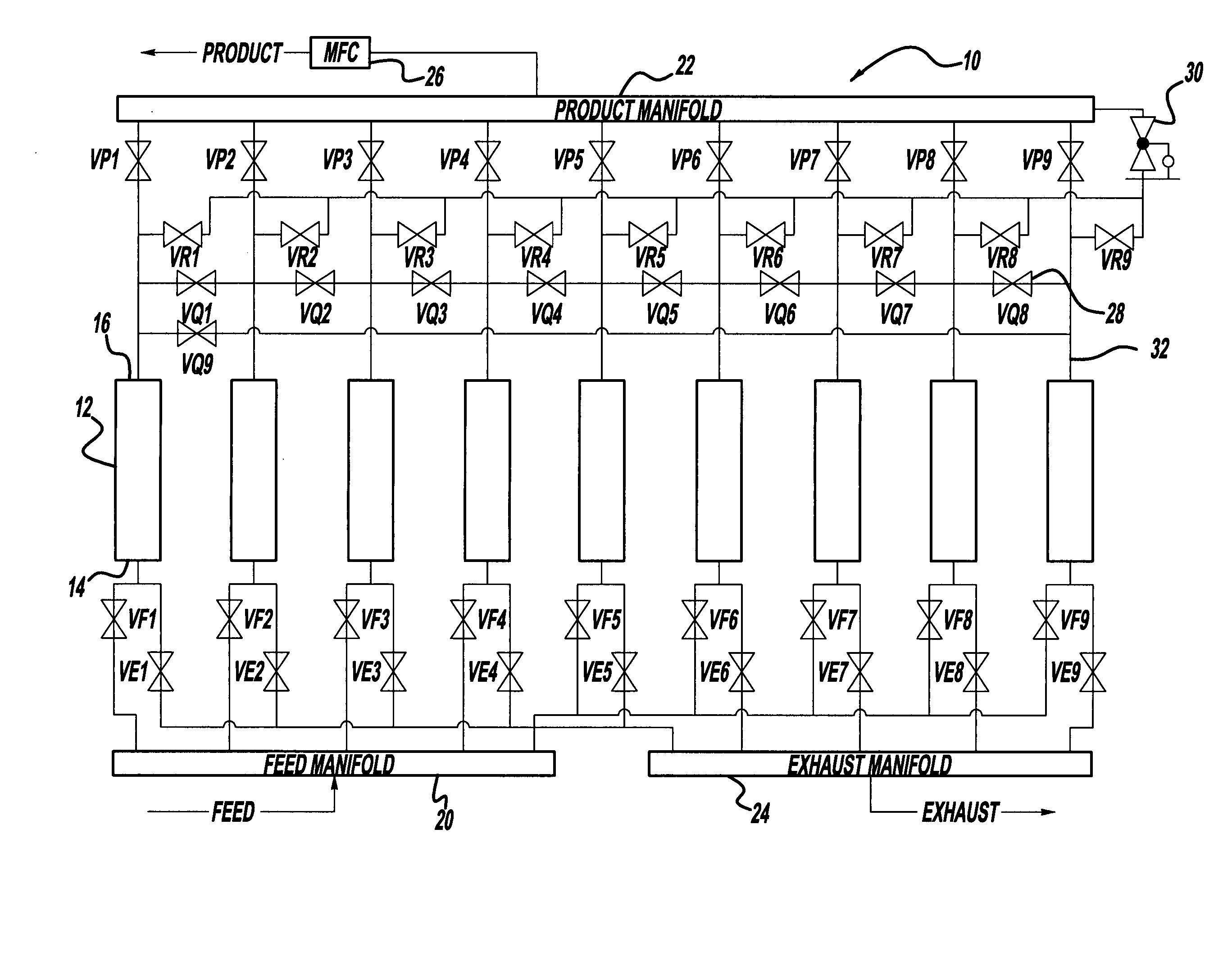
[0039]FIG. 1 is a plan view of a PSA system 10 for purifying a feed gas, such as a reformate gas, into a product gas, such as a purified hydrogen gas. The system 10 includes nine columns, beds or vessels 12 each having a feed end 14 that receives the feed gas and a product end 16 that emits the product gas. The vessels 12 include an adsorbent or mixture of adsorbents for adsorbing carbon monoxide, carbon dioxide, nitrogen, water, methane, etc. At least one adsorbent in the vessels 1...


PUM

PropertyMeasurementUnit
pressureaaaaaaaaaa
pressureaaaaaaaaaa
pressureaaaaaaaaaa

Abstract

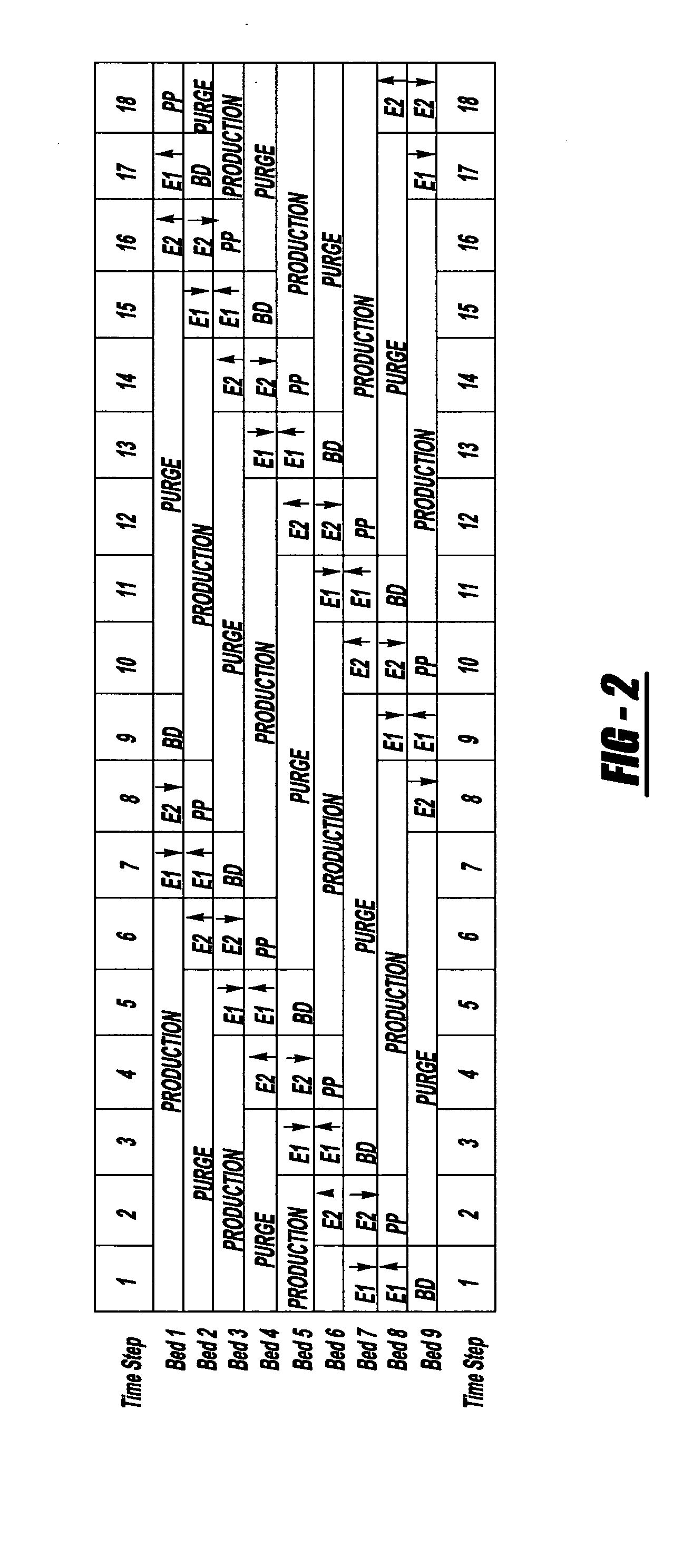
A PSA system that purifies a feed gas, such as a reformate gas in fuel cell system. The PSA system includes a series of vessels housing an adsorbent or combination of adsorbents that adsorb carbon monoxide, carbon dioxide, nitrogen, water and methane in the reformate gas. The adsorbent vessels are connected to each other and a feed manifold, a product manifold and an exhaust manifold through suitable conduits, where the gas flows are controlled by a product rotating valve and feed rotating valve or a series of open / shut valves. A specialized PSA cycle controls the valves so that the vessels cycle through various stages of equalization, blow-down, purge, pressurization and production to purify the feed gas.

Description

BACKGROUND OF THE INVENTION [0001] 1. Field of the Invention [0002] This invention relates generally to a pressure swing adsorption (PSA) system for purifying a gas and, more particularly, a PSA system for purifying hydrogen in a fuel cell system, where the PSA system employs a specialized PSA cycle. [0003] 2. Discussion of the Related Art [0004] Hydrogen is a very attractive fuel because it is clean and can be used to efficiently produce electricity in a fuel cell. The automotive industry expends significant resources in the development of hydrogen fuel cells as a source of power for vehicles. Such vehicles would be more efficient and generate fewer emissions than today's vehicles employing internal combustion engines. [0005] A hydrogen fuel cell is an electrochemical device that includes an anode and a cathode with an electrolyte therebetween. The anode receives hydrogen gas and the cathode receives oxygen or air. The hydrogen gas is disassociated in the anode to generate free hyd...

Claims


Application Information

Patent Timeline
Patent Type & Authority Applications(United States)
IPC IPC(8): B01D53/02B01D53/047C01B3/56
CPCB01D53/047Y02C20/20B01D2253/102B01D2253/104B01D2253/108B01D2256/16B01D2257/102B01D2257/304B01D2257/406B01D2257/50B01D2257/702B01D2257/7025B01D2257/80B01D2258/0208B01D2259/40005B01D2259/40007B01D2259/40041B01D2259/40052B01D2259/40069B01D2259/40073B01D2259/40075B01D2259/4061B01D2259/4066C01B3/56C01B2203/043C01B2203/0465C01B2203/047C01B2203/0475C01B2203/048C01B2203/0485C01B2203/0495C01B2203/066B01D53/261Y02P20/151Y02P20/156
Inventor GITTLEMAN, CRAIG S.APPEL, WILLIAM SCOTWINTER, DAVID PHILLIPSWARD, BRIAN KENNETH
Owner GENERAL MOTORS COMPANY
Learn More