
Hybrid power devices and switching circuits for high power load sourcing applications

a switching circuit and hybrid technology, applied in electronic switching, dc-dc conversion, pulse technique, etc., can solve the problems of more switching operations per output period, high switching loss, etc., and achieve the effect of efficient load current supply

Inactive Publication Date: 2014-07-03
EATON CORP
View PDF3 Cites 40 Cited by
  • Summary
  • Abstract
  • Description
  • Claims
  • Application Information

AI Technical Summary

Benefits of technology

The present invention provides high power switching devices that can efficiently handle both light and heavy loading conditions. These devices contain a hybrid switching circuit with two unequal bandgap semiconductor materials that can be driven with separate control signals. The control circuit ensures that the first and second switching devices are driven with different duty cycles, with the first duty cycle being longer than the second duty cycle. The invention also includes a control circuit for driving the first and second wide bandgap transistors with separate control signals, with the first duty cycle being longer than the second duty cycle. The invention can be used in various applications such as inverters and clamps, where high switching losses are typically encountered. The technical effects of the invention include improved load current provision and reduced switching losses.

Problems solved by technology

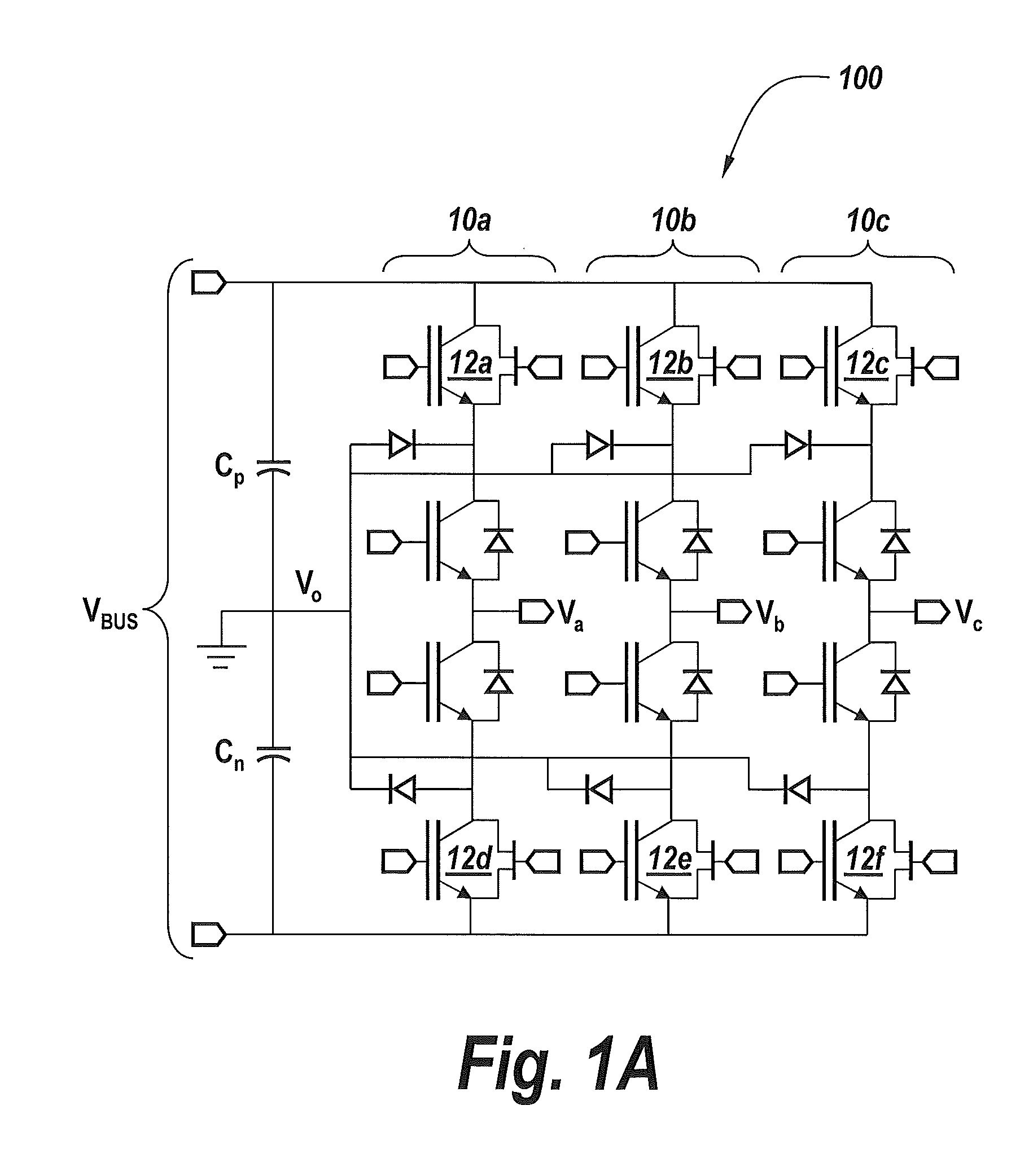
For example, in a neutral-point clamped (NPC) inverter (a / k / a “three-level inverter”), a hybrid switch may be used for the “outer” devices because these typically have higher switching losses (i.e., more switching operations per output period) than the “inner” devices.

Method used


Image

  • Hybrid power devices and switching circuits for high power load sourcing applications
  • Hybrid power devices and switching circuits for high power load sourcing applications
  • Hybrid power devices and switching circuits for high power load sourcing applications

Examples


Embodiment Construction

[0017]The present invention now will be described more fully with reference to the accompanying drawings, in which preferred embodiments of the invention are shown. This invention may, however, be embodied in many different forms and should not be construed as being limited to the embodiments set forth herein; rather, these embodiments are provided so that this disclosure will be thorough and complete, and will fully convey the scope of the invention to those skilled in the art. Like reference numerals refer to like elements throughout.

[0018]It will be understood that when an element or layer is referred to as being “on,”“connected to” or “coupled to” another element or layer (and variants thereof), it can be directly on, connected or coupled to the other element or layer or intervening elements or layers may be present. In contrast, when an element is referred to as being “directly on,”“directly connected to” or “directly coupled to” another element or layer (and variants thereof),...


PUM


Abstract

A hybrid switching circuit includes first and second switching devices containing first and second unequal bandgap semiconductor materials. These switching devices, which support parallel conduction in response to first and second control signals, are three or more terminal switching devices of different type. For example, the first switching device may be a three or more terminal wide bandgap switching device selected from a group consisting of JFETs, IGFETs and high electron mobility transistors HEMTs, and the second switching device may be a Si-IGBT. A control circuit is also provided, which is configured to drive the first and second switching devices with first and second periodic control signals having first and second unequal duty cycles. The first duty cycle may be greater than the second duty cycle and the active phases of the second periodic control signal may occur exclusively within the active phases of the first periodic control signal.

Description

FIELD OF THE INVENTION[0001]The present invention relates to integrated circuit devices and, more particularly, to integrated circuit devices for power switching applications.BACKGROUND OF THE INVENTION[0002]Wide bandgap (WBG) power devices such as SiC and GaN power devices can provide superior performance characteristics relative to Si power devices for many high power applications. For example, as disclosed in an article by J. Burm et al., entitled “Wide Band-Gap FETs for High Power Amplifiers,” Journal of Semiconductor Technology and Science, Vol. 6, No. 3, pp. 175-182, September (2006), wide bandgap semiconductor materials having band-gap energy levels in a range from about 2 eV to about 6 eV may be utilized to provide high breakdown voltages for high power generation in power amplifiers and low dielectric constants for better isolation and lower coupling. Similarly, as disclosed in an article by J. Reed et al., entitled “Modeling Power Semiconductor Losses in HEV Powertrains us...

Claims


Application Information

Patent Timeline
IPC IPC(8): H03K17/56H01L29/739H02M7/537H01L29/16
CPCH03K17/56H01L29/1602H02M7/537H01L29/7393H01L29/1608H03K17/127H03K17/567H03K2217/0036H02M7/487H02M3/155
Inventor LIU, YUHO, ANDRAWLEE, NASHKRSTIC, SLOBODAN
Owner EATON CORP
Learn More