
Anisotropic conductive film, production method thereof and method of use thereof

Inactive Publication Date: 2005-04-14
NITTO DENKO CORP
View PDF25 Cites 28 Cited by
  • Summary
  • Abstract
  • Description
  • Claims
  • Application Information

AI Technical Summary

Benefits of technology

In view of the above-mentioned situation, the present invention mainly aims at providing an anisotropic conductive film affording a fine contact between a terminal of a connection target and a conductive path by simply applying a relatively low load to a connection target having a narrow-pitched terminal, particularly a connection target having a narrow pitch and a terminal disposed far back from the surface of the component and a production method thereof. In another aspect, the present invention mainly aims at providing an anisotropic conductive film for an electronic component test, which is unlikely to stain an electrode of a test subject electronic component and the surface of a circuit pattern of a circuit board, in a wide temperature range of from 20° C. to 150° C. The present invention also aims at providing a highly reliable test method of an electronic component using an anisotropic conductive film.

Problems solved by technology

However, since the anisotropic conductive film disclosed in JP-A-2002-42921 aims only at increasing the proportion of a resin in a film, the distance between adjacent conductive paths (proportion of insulated area) in an anisotropic conductive film becomes too large, which makes sufficient application thereof to a narrow pitch terminal of a connection target (electronic component, circuit board) unattainable.
In connection with the above, the present inventors have found that, when an anisotropic conductive film is to be used, problems occur such as a contact failure between electrodes, “staining of metal electrode” and the like in a conduction test of an electronic component at a high temperature.
Even when a simple conduction test using an electrically conductive rubber is conducted, a problem of failure to mount an electronic component and a circuit board occurs.

Method used


Image

  • Anisotropic conductive film, production method thereof and method of use thereof
  • Anisotropic conductive film, production method thereof and method of use thereof
  • Anisotropic conductive film, production method thereof and method of use thereof

Examples


first embodiment

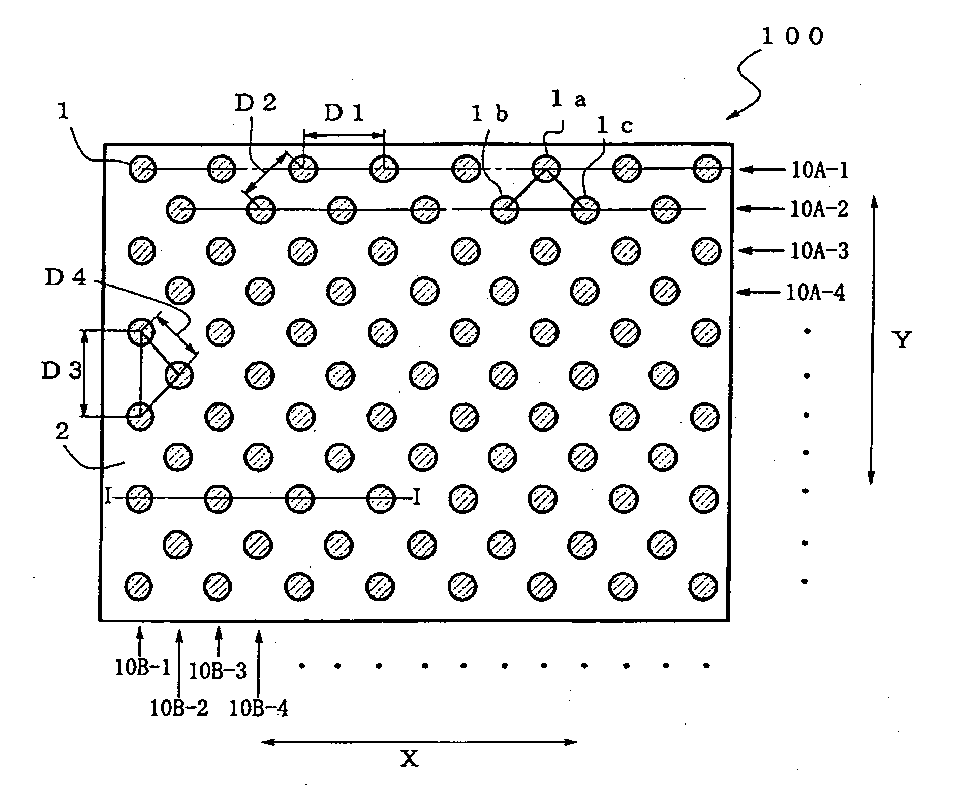
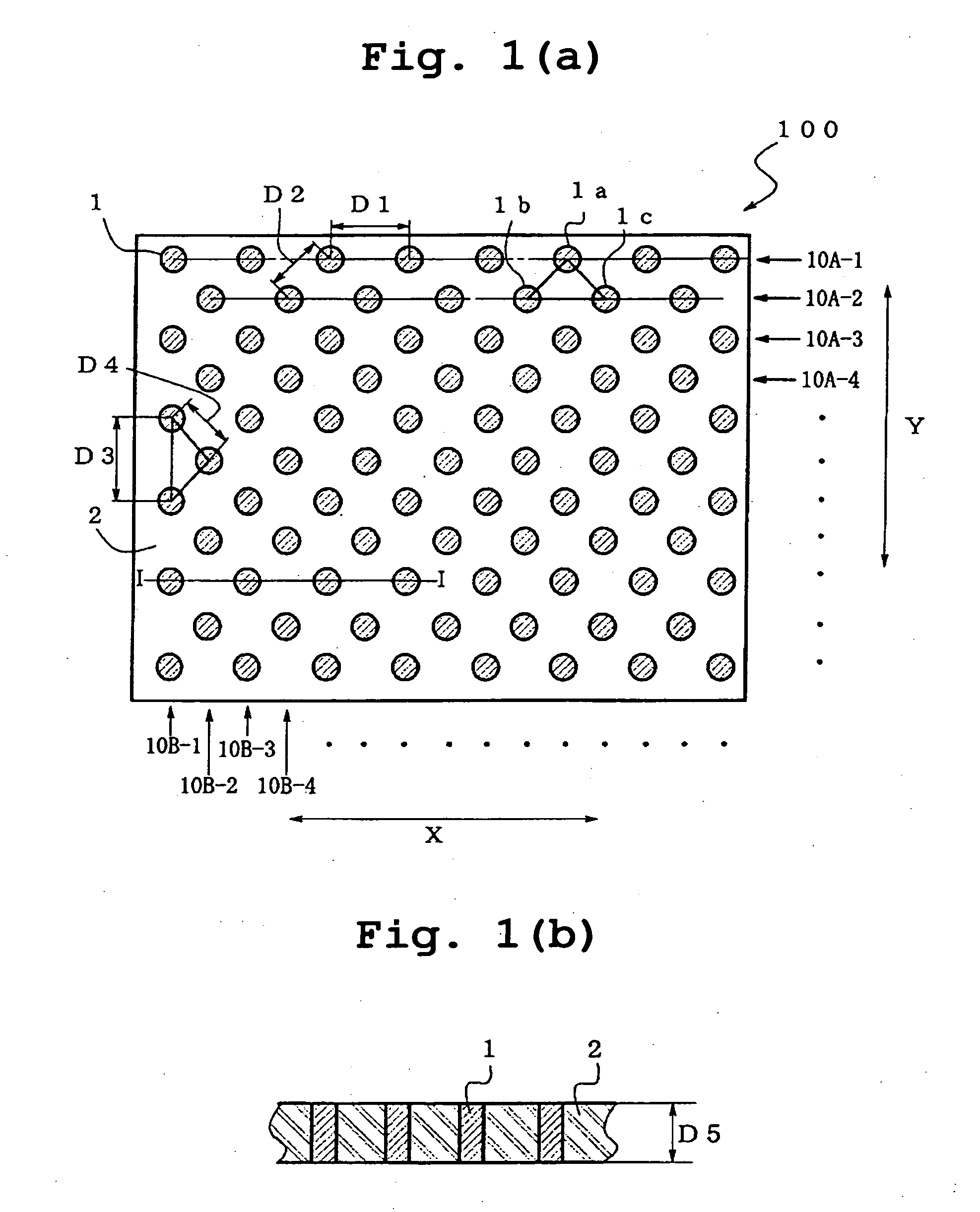
FIG. 1 schematically shows a first embodiment of the anisotropic conductive film of the present invention, wherein FIG. 1(a) is a plane view, and FIG. 1(b) is a sectional view of FIG. 1(a) along line I-I.

As used herein, the “houndstooth check” means the same as the “houndstooth check” used in various uses for electric or electronic connectors and the like to mean arrangement pattern of terminals and pins. For example, in FIG. 1, conductive paths 1 form rows of conductive paths (10A-1, 10A-2, 10A-3, 10A-4, . . . ) arranged in parallel to each other at a given pitch in one direction (e.g., direction Y in FIG. 1) of the principal plane of the film, and the position of respective conductive paths 1 constituting the odd-numbered rows of conductive paths (10A-1, 10A-3, . . . ) is out of alignment by about ½ pitch toward the aligning direction (direction X in FIG. 1) of the conductive path 1 from the position of respective conductive paths 1 constituting the even-numbered rows of conduct...

second embodiment

In a different preferable embodiment (second embodiment), the anisotropic conductive film 100 of the present invention comprises, as the one described in WO98 / 07216, a plate film substrate 2 made from an insulating material and the conductive paths 1 penetrating the film substrate 2 in the thickness direction while being insulated from each other. In the second embodiment, the above-mentioned film substrate 2 comprises resin and rubber described in detail in the following. FIG. 7 schematically shows a test of an electronic component using this anisotropic conductive film.

The film substrate 2 comprises an acrylic rubber and a naphthalene skeleton epoxy resin crosslinked with a phenol resin. Each resin is described in detail below. As a result of the action of a phenol resin as a crosslinking agent on a naphthalene skeleton epoxy resin, the film substrate 2 shows heat resistance and the presence of an acrylic rubber allows simultaneous expression of flexibility. A method to obtain ...

example 1

An aluminum cylindrical core having a diameter of 320 mm and a length of 270 mm is set on a horizontal type regular winding machine (HPW-02, Nittoku Engineering Co., Ltd.), on which a 50 μm-thick fluorocarbon resin film as a slip film and a film consisting of a 50 μm-thick thermoplastic polyurethane elastomer having a rubber hardness of 75 degrees (Esmer URS, Nihon Matai Co., Ltd., softening temperature 60° C.) were wound, and a heat-resistant polyurethane coated wire (copper wire (diameter 25 μm) coated with heat resistant polyurethane in 2 μm thickness) having a diameter of 29 μm was wound 250 mm at a winding intervals (pitch) of 100 μm. Then, after winding a thermoplastic polyurethane elastomer film similar to the above, winding of heat resistant polyurethane coated wire was further repeated 54 times, during which the odd-numbered layers of wound wires and even-numbered layers of wound wires from the core side were displaced such that the start position of the insulation wire wi...


PUM


Abstract

The present invention provides an anisotropic conductive film for testing an electronic component, which comprises a film substrate comprising an insulating resin and plural conductive paths insulated from each other and penetrating the film substrate in the thickness direction, preferably, an anisotropic conductive film wherein the plural conductive paths are disposed in a houndstooth check pattern and the distance between conductive paths between adjacent rows of conductive paths is smaller than the distance between conductive paths within a row of conductive paths. In another preferable embodiment, the insulating resin comprises a naphthalene skeleton epoxy resin crosslinked with a phenol resin and an acrylic rubber, and both ends of the plural conductive paths are exposed on both the front and the back surfaces of the film substrate.

Description

FIELD OF THE INVENTION The present invention relates to an anisotropic conductive film, a production method thereof and a test method of an electronic component using the same. BACKGROUND OF THE INVENTION For an electrical connection between an electronic component such as a semiconductor element (IC chip) and the like and a circuit board, an anisotropic conductive connector has been widely used in recent years. As an anisotropic conductive connector, one prepared by dispersing conductive fine particles in an insulating film has been conventionally known. This anisotropic conductive connector is associated with problems of structurally difficult connection with a connection target having a fine pitch and the need for forming a terminal of the connection target, such as electrode of semiconductor element and the like in a protrusion (bump). Thus, as an anisotropic conductive connector capable of resolving such problems, namely, an anisotropic conductive connector capable of dealing...

Claims


Application Information

Patent Timeline
IPC IPC(8): G01R1/073H01R11/01H01L21/48H01L21/60H01L23/498H01R13/24H01R43/00
CPCG01R1/0735G01R1/07371H01L2924/0665H01L2924/014H01L2924/01087H01L2924/01006G01R3/00H01L21/486H01L23/49827H01L24/28H01L24/83H01L2224/838H01L2924/01002H01L2924/01005H01L2924/01013H01L2924/01018H01L2924/01027H01L2924/01029H01L2924/01033H01L2924/01057H01L2924/01073H01L2924/01074H01L2924/01078H01L2924/01079H01L2924/0781H01L2924/14H01R13/2414H01L2224/2919H01L2924/00H01L2924/12042H01L2224/81101H01R11/01H01R43/00
Inventor ASAI, FUMITERUNORO, MASATO
Owner NITTO DENKO CORP
Learn More