LED lamp module and method for manufacturing the same

Inactive Publication Date: 2005-03-24
YAZAKI CORP
View PDF11 Cites 42 Cited by
  • Summary
  • Abstract
  • Description
  • Claims
  • Application Information

AI Technical Summary

Benefits of technology

[0016] The LED lamp 70 is connected with the electric wire 83 by pressure contact so that manufacturability for connecting is much improved against by soldering. However, when the LED lamp is used for a tail lamp of a vehicle instead of a usual electric light bulb, at least five LED lamps 70 are required. Therefore, a connecting method with further better manufacturability is expected.
[0029] According to above structure, the resin lens can be molded with epoxy resin advantageous on light transmissivity, moldability and dimensional stability, and the lamp holder can be molded with one of poly butylene terephthalate (PBT) and polypropylene (PP) advantageous on heat resistance, moldability, insulation performance and strength. Thereby, the LED lamp module with the resin lens and lamp holder meeting respective performances can be provided.

Problems solved by technology

If the LED lamp is mounted directly on a flat circuit board by soldering, a illuminating device may be structured by disposing a plurality of LED lamps in a flat surface so that flexibility of disposition of LED lamps is limited.

Method used


Image

  • LED lamp module and method for manufacturing the same
  • LED lamp module and method for manufacturing the same
  • LED lamp module and method for manufacturing the same

Examples


first embodiment

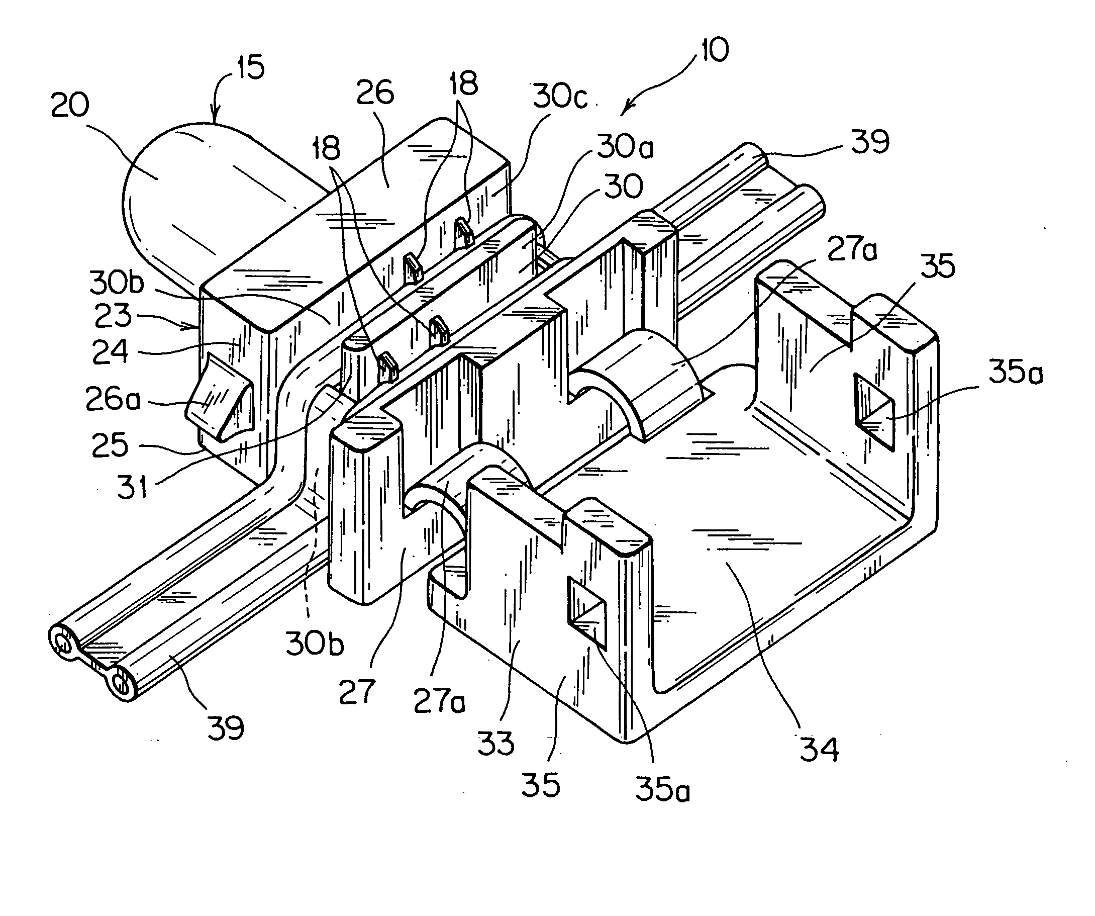
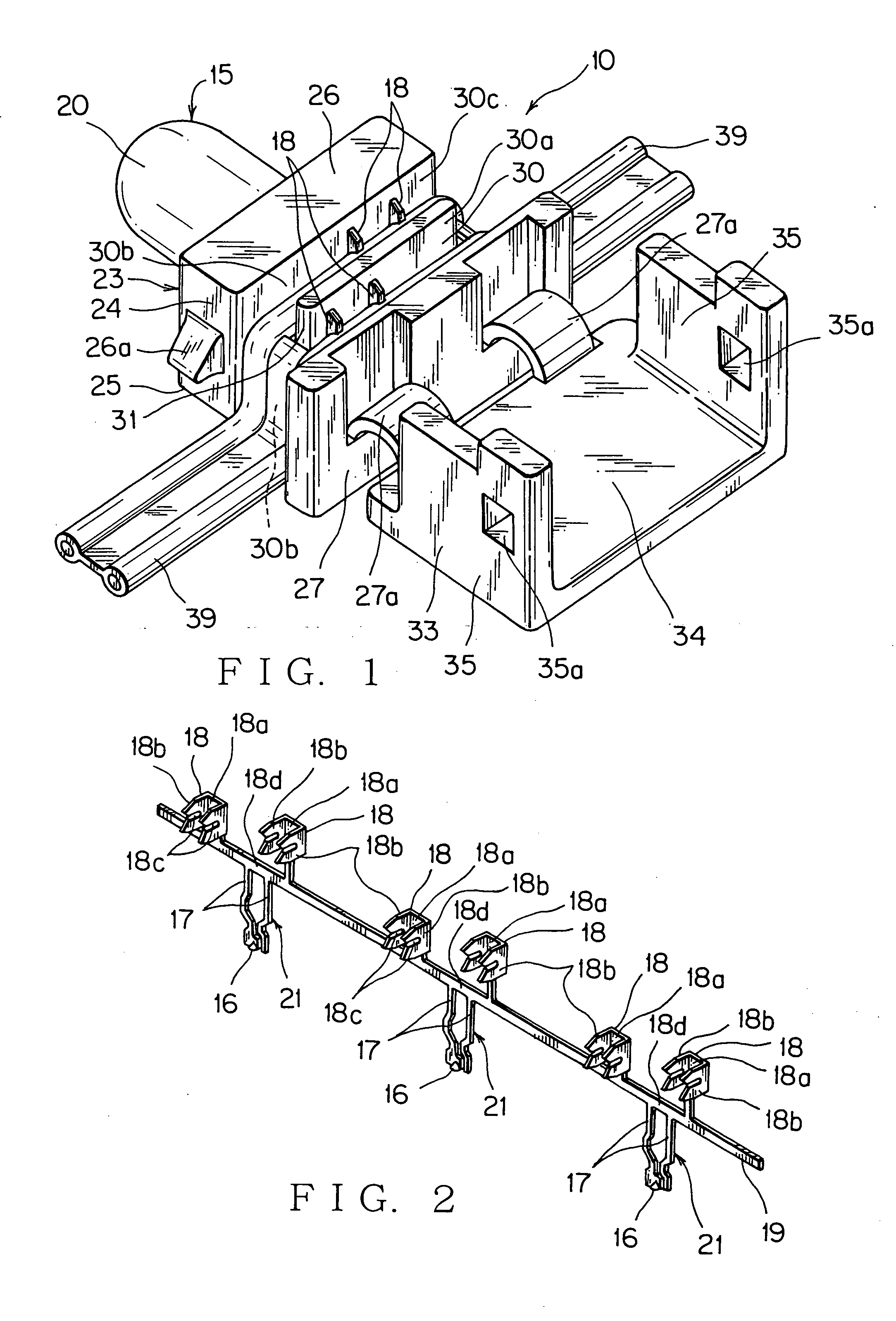
[0045] The LED lamp module 10 of the first embodiment can connect the lead terminal 17 and the electric wire 39 without soldering so that manufacturability of connecting is improved. 10 Deformation such as the inclination of an electric-wire pressure contact portion 18 and breakage of a resin lens 20 can be prevented, and the LED lamp module 10 can be disposed freely without limitation of mounting position thereof. An LED lamp 15 include an LED chip 16, a plurality of lead terminals 17 having the electric wire pressure contact portion 18 to be connected with an outer electric wire 39 and supplying source current to the LED chip 16, and a resin lens 20 sealing the LED chip 16. The LED lamp 15 and a lamp holder 23 holding the LED lamp 15 are molded integrally as the LED lamp module 10. Preferably, the resin lens 20 and the lamp holder 23 are molded with two different colors of synthetic resins. The LED lamp module 10 has the aforesaid first features. The lamp holder 23 can be also str...

second embodiment

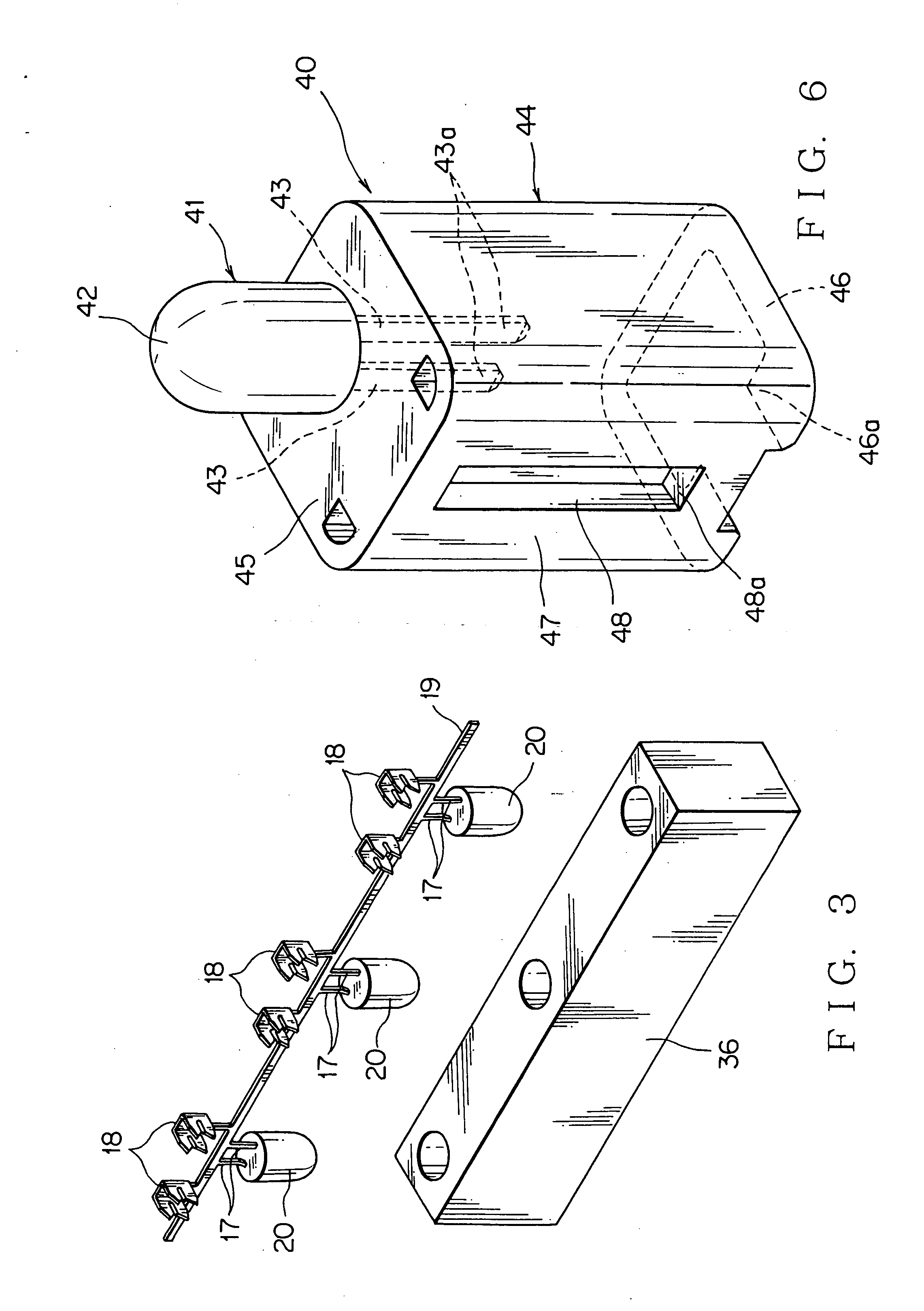
[0046] In the LED lamp module 40 of the second embodiment, by connecting the lamp holder 44 with a not-shown mating connector at power supply side, the LED lamp 41 and an electric wire 39 can be connected electrically by one action. The LED lamp module has the second features that a connector 46a connecting with a mating connector is formed at the lamp holder 44 and a tab-shape electric contact portion 43a continued to the lead terminal 43 projects into the connector 46a.

[0047] Main components and their actions of the LED lamp module 10 as the first embodiment are described hereafter. The LED lamp module 10 includes the LED lamp 15 and the lamp holder 23 holding the LED lamp 15.

[0048] The LED lamp 15 is structured with the LED chip 16 for a light source, a pair of lead terminal 17 and the resin lens 20 sealing the LED chip 16 (FIG. 3). The LED chip 16 is a semiconductor emitting light with a reduced voltage by a not-shown current-limit resistor or a not-shown current regulative di...


PUM


Abstract

Providing an LED lamp module and a method of manufacturing the module preventing deformation and having more freedom for disposing the module, an LED chip for light source, lead terminals having electric-wire pressure contact to be connected with electric wires 39 and supplying source current to the LED chip, an LED lamp 15 including a resin lens 20 sealing the LED chip, and a lamp holder 23 holding the LED chip 15 are molded integrally. Preferably, the resin lens 20 and the lamp holder 23 are molded with different synthetic resin materials by double molding. A connector to be connected with a mating connector is formed at the lamp holder and tab-like terminals continued to the lead terminals project into the connector.

Description

[0001] The priority application Number Japan Patent Application Laid Open 2003-328123 upon which this patent application is based is hereby incorporated by reference. BACKGROUND OF THE INVENTION [0002] 1. Field of the Invention [0003] This invention relates to an LED lamp module used for illuminating an inside of a car cabin, a glove compartment, such as a console box, a glove box, a pocket and an ashtray, a cup holder, a foot area as a light source of an internal light, and used for a stop lamp and a tail lamp as a light source of an external light, and a method of manufacturing the LED lamp module. [0004] 2. Description of the Related Art [0005] An LED (Light Emitting Diode) has at least two lead terminals at plus side and minus side. The LED is a semiconductor emitting light in which current of a few mA flows at a few volts depending on a lighting color by supplying a forward voltage, i.e. positive voltage on the lead terminal at plus side and negative voltage on the lead termina...

Claims


Application Information

Patent Timeline
IPC IPC(8): F21S8/10F21V19/00F21V5/04F21V21/002F21Y101/02H01L33/56H01L33/58H01L33/62H01R4/24H01R13/717H01R33/06
CPCB60Q3/0203F21S48/212F21V21/002F21Y2101/02H01R33/06H01R13/717H01R13/7172H01R13/7175H01R4/2433F21Y2115/10B60Q3/51F21S43/195
Inventor CHIBA, SHINGOMATSUSHITA, HARUYUKI
Owner YAZAKI CORP
Why Eureka
Try Eureka