
Catheter balloon formed of ePTFE and a diene polymer

a polymer and diene technology, applied in the field of medical devices, can solve the problems of fusion bonding of dissimilar materials to substrate materials that can be extremely difficult, trauma to the vessel wall, etc., and achieve the effects of improving performance characteristics, low profile deflated configuration, and high strength

Inactive Publication Date: 2005-09-20
ABBOTT CARDIOVASCULAR
View PDF36 Cites 90 Cited by
  • Summary
  • Abstract
  • Description
  • Claims
  • Application Information

AI Technical Summary

Benefits of technology

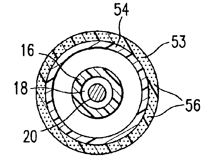
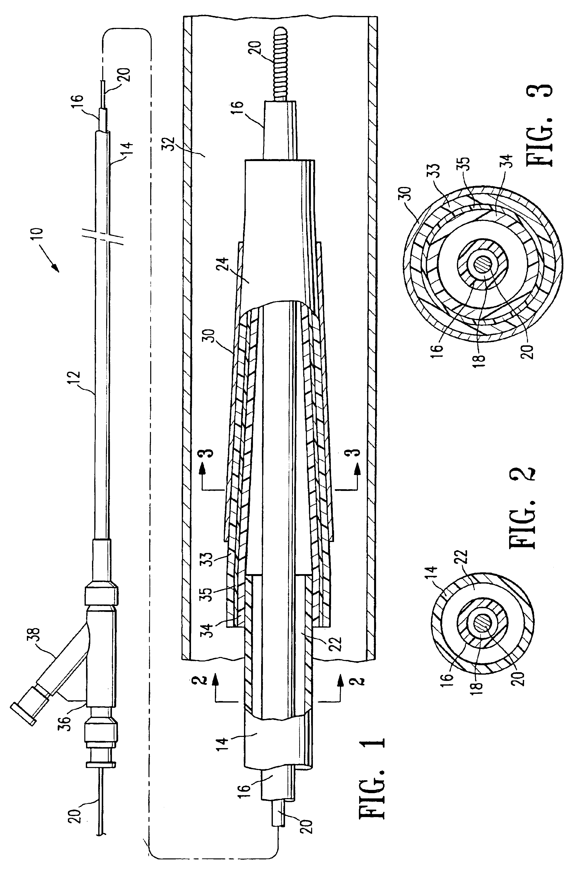
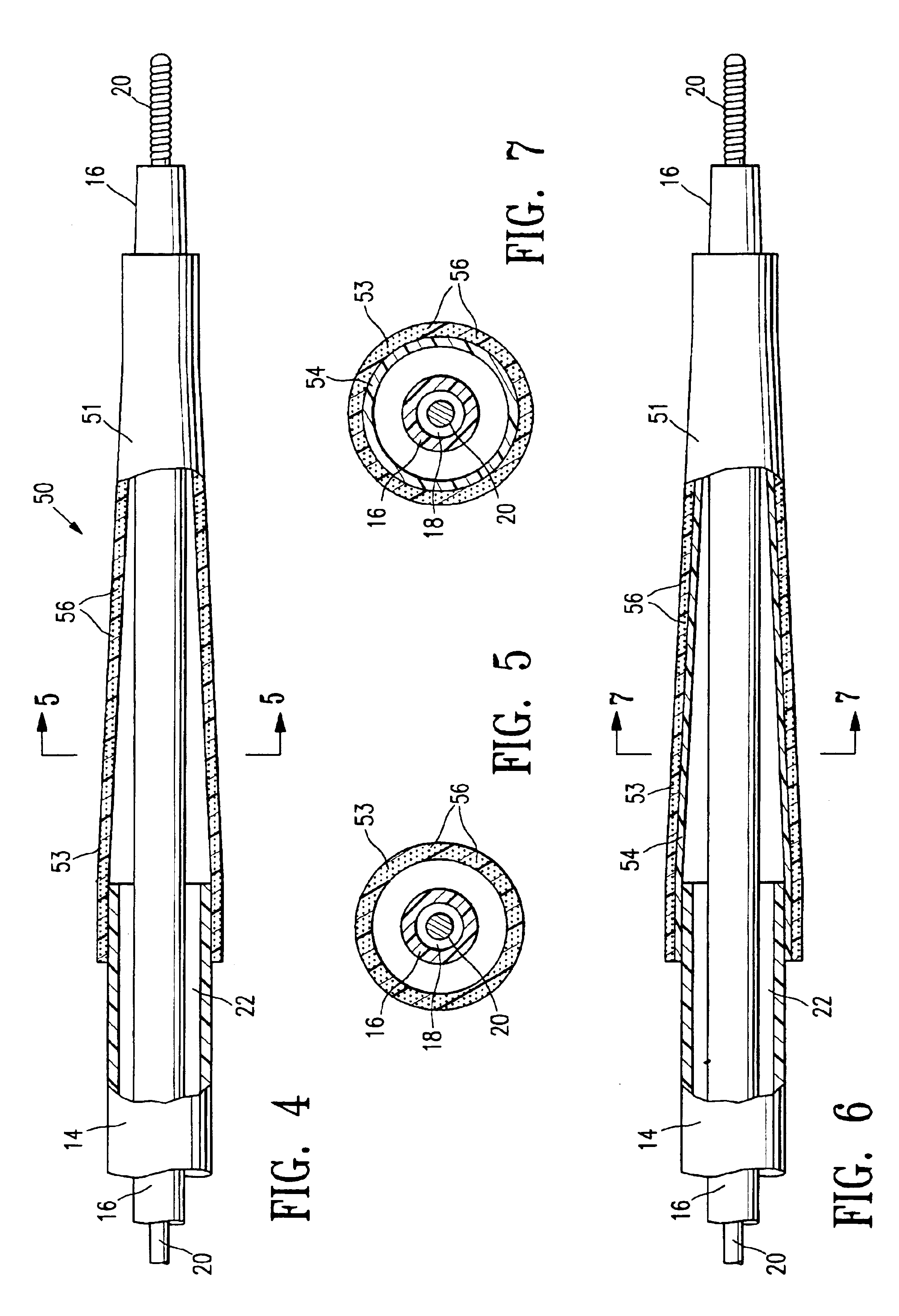
[0006]This invention is directed to a catheter balloon formed of a polymeric material such as expanded polytetrafluoroethylene (ePTFE) bonded to a second layer formed of a low tensile set polymer and / or impregnated with a low tensile set polymer. In a presently preferred embodiment, the low tensile set polymer is an elastomer selected from the group consisting of a silicone-polyurethane copolymer and a diene polymer. The low tensile set polymer has high strength, low modulus, high elongation, and low tensile set, to provide improved balloon performance. Specifically, the silicone-polyurethane or diene has a low tensile set which facilitates deflation of the balloon to a low profile deflated configuration. In a presently preferred embodiment, the balloon has a low radial tensile set of about 1% to about 20%, preferably about 1% to about 10%.
[0021]The balloon of the invention has improved performance characteristics such as a low profile deflated configuration, high strength, flexibility and conformability, and improved manufacturability. Additionally, the balloon has excellent adhesion between the ePTFE (or other polymer) and the silicone-polyurethane copolymer or diene polymer, with minimal effect on the structural integrity of the ePTFE material, unlike chemical modification involving decomposition of the ePTFE. These and other advantages of the invention will become more apparent from the following detailed description when taken in conjunction with the accompanying exemplary drawings.

Problems solved by technology

Substantial, uncontrolled expansion of the balloon against the vessel wall can cause trauma to the vessel wall.
In the manufacture of catheters, one difficulty has been the bonding of dissimilar materials together.
The fusion bonding of a dissimilar material to a substrate material can be extremely difficult if the substrate has a low surface energy.
For example, lubricious materials such as HDPE and PTFE, often used to form inner tubular members of catheters to provide good guidewire movement therein, have low surface energies of 31 dynes / cm and 18 dynes / cm, respectively, that make bonding to balloons formed of a dissimilar material such as a polyamide difficult.
However, a decrease in shaft collapse pressure resistance may result in some cases when the outer layer has a low stiffness.
While adhesives may be used in some cases to bond dissimilar materials together, they are not ideal because they can increase stiffness of the component at the bond and some materials do not bond well to adhesives commonly used in medical devices.
However, ePTFE has proven difficult to bond to balloon liner materials and / or to catheter shafts.
One difficulty has been bonding ePTFE absent the use of adhesives and / or some pretreatment causing decomposition of the fibril structure.

Method used


Image

  • Catheter balloon formed of ePTFE and a diene polymer
  • Catheter balloon formed of ePTFE and a diene polymer
  • Catheter balloon formed of ePTFE and a diene polymer

Examples


example i

[0043]Catheter balloons were prepared having a first layer of ePTFE with a plasma polymerized acrylic acid functionality (i.e., bondable material), and a second layer of a diene polymer and AMBT (i.e., a bonding promoter), as follows. 30 grams of Kraton 1611K styrene-isoprene-styrene block copolymer was mixed in 166 grams of THF, and to this mixture was added 0.92 grams of 6-amino 2-mercaptobenzothiazole (AMBT) from Aldrich. The solution was put on an agitator for 12 hours to ensure the formation of a uniformly dissolved solution. A Teflon coated mandrel having an outer diameter of about 0.026 inches was dip coated with the solution, and dried, and the resulting coating was removed from the mandrel, to produce a tube formed of the diene-AMBT mixture having an inner diameter of about 0.026 inch and an outer diameter of about 0.032 inch. The length of the diene-AMBT tube was trimmed to about 2 inches, and the diene-AMBT tube was placed over a balloon catheter shaft in preparation for ...

example ii

[0046]Catheter balloons were prepared having a first layer of ePTFE impregnated with a diene-AMBT mixture (i.e., a bondable material), and a second layer of a diene polymer and AMBT (i.e., a bonding promoter), as follows. Diene-AMBT tubes were made using the dip coat method set forth above in Example I. A portion of the Kraton / THF / AMBT solution prepared was taken and diluted with THF in a 1:1 ratio to produce a solution having about 7.5% by weight of Kraton dissolved in THF. A 0.034 inch Teflon mandrel wet with the Kraton / THF / AMBT solution was slid into the inner lumen of a ePTFE tube, to expose the ePTFE tube to the solution. Uniform coating was produced by manually pressing the ePTFE tube along the entire length onto the mandrel to ensure good contact. The mandrel was removed and dry nitrogen at less than 20 psi was blown through the inner lumen of the ePTFE tube to evaporate the solvent. The Kraton / AMBT mixture is believed to form an interpenetrating network through the pores of ...


PUM

PropertyMeasurementUnit
elongationaaaaaaaaaa
tensile strengthaaaaaaaaaa
pressuresaaaaaaaaaa

Abstract

A catheter balloon formed of a polymeric material such as expanded polytetrafluoroethylene (ePTFE) bonded to a second layer formed of a low tensile set polymer and / or impregnated with a low tensile set polymer. In a presently preferred embodiment, the low tensile set polymer is a silicone-polyurethane copolymer elastomer or a diene polymer elastomer. The low tensile set polymer has high strength, low modulus, high elongation, and low tensile set. The diene or silicone-polyurethane has a low tensile set, which facilitates deflation of the balloon to a low profile deflated configuration. One aspect of the invention provides improved attachment of the diene to the ePTFE. In one embodiment, the second layer is formed of a diene mixed with a bonding promoter such as a vulcanizing agent which is covalently bonded to the diene.

Description

BACKGROUND OF THE INVENTION[0001]This invention generally relates to medical devices, and particularly intracorporeal devices for therapeutic or diagnostic uses, such as balloon catheters. In percutaneous transluminal coronary angioplasty (PTCA) procedures, a guiding catheter is advanced until the distal tip of the guiding catheter is seated in the ostium of a desired coronary artery. A guidewire, is first advanced out of the distal end of the guiding catheter into the patient's coronary artery until the distal end of the guidewire crosses a lesion to be dilated. Then the dilatation catheter having an inflatable balloon on the distal portion thereof is advanced into the patient's coronary anatomy, over the previously introduced guidewire, until the balloon of the dilatation catheter is properly positioned across the lesion. Once properly positioned, the dilatation balloon is inflated with fluid one or more times to a predetermined size at relatively high pressures (e.g., greater tha...

Claims


Application Information

Patent Timeline
Patent Type & Authority Patents(United States)
IPC IPC(8): A61L29/00A61L29/04A61M25/10A61L29/08A61L29/12A61F2/958A61M25/00A61M25/16
CPCA61L29/041A61L29/126A61M25/1006A61M25/1025A61M25/1029A61M25/1034A61L29/085C08L27/18Y10T428/1393A61M2025/1075Y10T428/1376Y10T428/1352Y10T428/1386Y10T428/139Y10T428/1334Y10T428/13
Inventor LIM, FLORENCIALONG, CHI LECLAUDE, CHARLES D.LEE, JEONG S.SRIDHARAN, SRINIVASANGONZALEZ, FERNANDOWANG, EDWIN
Owner ABBOTT CARDIOVASCULAR
Learn More