
Support material for three-dimensional laminating molding

a technology of support material and three-dimensional laminating, which is applied in the direction of additive manufacturing processes, manufacturing tools, electric/magnetic/electromagnetic heating, etc., can solve the problems of increasing the start-up time of the device and the electric power consumption of the device when driving the device, and achieves high speed, high precision, and increased device start-up time.

Inactive Publication Date: 2005-03-10
RICOH PRINTING SYST
View PDF2 Cites 62 Cited by
  • Summary
  • Abstract
  • Description
  • Claims
  • Application Information

AI Technical Summary

Benefits of technology

[0022] Further, a melting point and an ink ejection temperature must be high, and an inkjet head, an ink channel, and an ink tank must be maintained at high temperatures when a material which is solid at room temperature and converts to liquid when heated used as a support material, thereby increasing a start-up time of the device and electric power consumption when driving the device.
[0023] It is an object of the present invention to overcome the above problems, and to provide a support material for three-dimensional laminating molding and an intermediate in the formation of a three dimensional laminated mold, which enable a three-dimensional laminating molding device to form a highly precise mold having a complex three-dimensional structure at high speed with suppressed electric power consumption and to shorten a start-up time of the device.
[0024] It is also an object of the present invention to provide a laminating molding method and a laminating molding device for producing a highly-precise three-dimensional lamination mold having a complex three-dimensional structure at high speed with a short start-up time and less electric power consumption.

Problems solved by technology

However, inkjet-type laminating molding devices commercially available at present are not meeting those needs of users.
Further, a melting point and an ink ejection temperature must be high, and an inkjet head, an ink channel, and an ink tank must be maintained at high temperatures when a material which is solid at room temperature and converts to liquid when heated used as a support material, thereby increasing a start-up time of the device and electric power consumption when driving the device.

Method used


Image

  • Support material for three-dimensional laminating molding
  • Support material for three-dimensional laminating molding
  • Support material for three-dimensional laminating molding

Examples


experiment 1

[0125] Experiment 1

[0126] A total of 300 g containing 10 parts by weight of urethane acrylate (trade name: DIABEAM UK6038, available from Mitsubishi Rayon Co., Ltd.) and 90 parts by weight of neopentyl glycol hydroxypivalate ester di(meth)acrylate (trade name: KAYARAD MANDA, available from Nippon Kayaku Co., Ltd.) as a mold material, 3 parts by weight of a photo-polymerization initiator (trade name: IRGACURE 1700, available from Ciba Specialty Chemicals), and 2 parts by weight of a blue pigment (trade name: Lionel Blue 7400G, available from TOYO INK MFG. CO., LTD.) as a colorant was dispersed until a uniform mixture was obtained using a homogenizer (trade name: HG30, manufactured by Hitachi Koki Co., Ltd.) at a stirring speed of 2,000 rpm. Successively, the resultant mixture was passed through a filter to remove impurities or the like, thereby obtaining a uniform ink composition for a mold (mold material).

[0127] A total of 300 g containing 100 parts by weight of hydrogenated palm o...

second experiment

[0138] Second Experiment

[0139] A total of 300 g containing 90 parts by weight of hydrogenated palm oil fatty triglyceride which is hydrogenated animal or vegetable oil or fat, RIKEMAL VT (MITI No. 8-358, available from Riken Vitamin Co., Ltd.) and 10 parts by weight of Kawaslip SA (available from Kawaken Fine Chemicals Co., Ltd.), both as support materials, and 3 parts by weight of a black pigment (MA77) was dispersed in the same manner as in the first experiment until a homogeneous mixture was obtained using a homogenizer (HG30, manufactured by Hitachi Koki Co., Ltd.) at a stirring speed of 2,000 rpm. Successively, filtration was carried out to remove impurities or the like, to thereby obtain a homogeneous ink composition for a support (support material). The composition had a melting point of 65 to 68° C. The support material in the second experiment had a density of 961.5 kg / m3 at 20° C., a density of 854.3 kg / m3 at the ejection temperature, and thus, a density ratio of 11.1%.

[0...

ninth experiment

[0154] Ninth Experiment

[0155] A total of 300 g containing 50 parts by weight of myristyl myristate, Crodamol MM (MITI No. 9-1382, available from Croda Japan K.K.) and 50 parts by weight of Kawaslip SA (available from Kawaken Fine Chemicals Co., Ltd.), both as support materials, and 3 parts by weight of a black pigment (MA77) as a colorant was dispersed in the same manner as in the first experiment until a uniform mixture was obtained using a homogenizer (HG30, manufactured by Hitachi Koki Co., Ltd.) at a stirring speed of 2,000 rpm. Successively, filtration was carried out to remove impurities or the like, to thereby obtain a uniform ink composition for a support (support material.

[0156] The support material had a melting point of 62 to 68° C. and a density ratio of 13.5%.

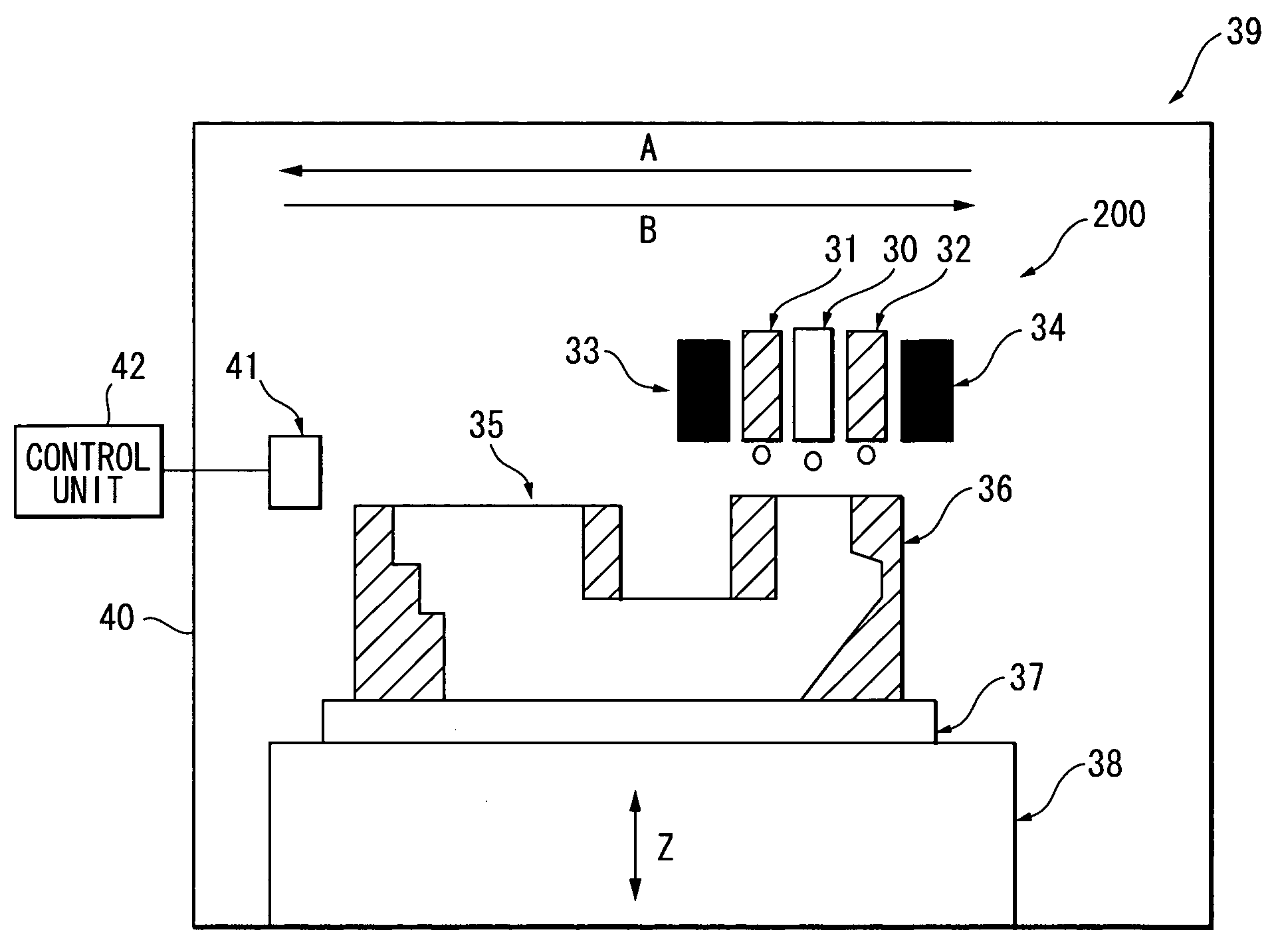
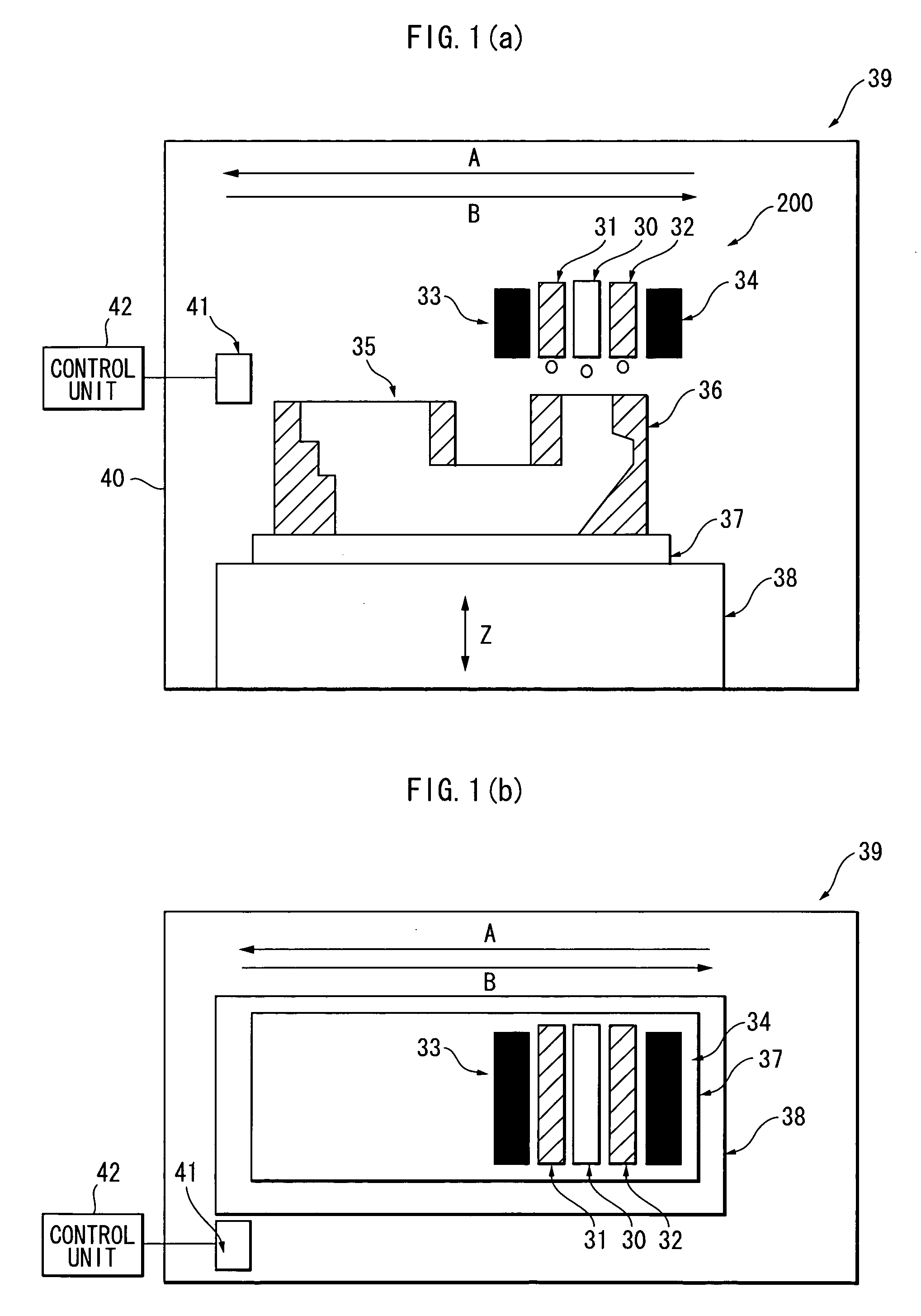
[0157] Mold formation was carried out by: using the same mold material as that in the first experiment and the molding device 39A shown in FIG. 6; and curing the mold material through irradiation using an ultravi...


PUM

PropertyMeasurementUnit
Temperatureaaaaaaaaaa
Fractionaaaaaaaaaa

Abstract

A three-dimensional laminated mold is formed by ejecting a mold material into a groove formed in a support. The support is formed from a support material ejected from an inkjet head. The support material has a ratio of density difference of equal to or less than 13.5%. The ratio of density difference is calculated from an equation: ratio of density difference=((D1-D2) / D1)×100 wherein D1 indicates the density of the support material at 20° C., and D2 indicates the density of the support material at a temperature at which a viscosity of the support material measured using a rotational viscometer falls within the range of 10±1 mPa·s.

Description

BACKGROUND OF THE INVENTION [0001] 1. Field of the Invention [0002] The present invention relates to a support material for three-dimensional laminating molding and an intermediate in the formation of a three-dimensional laminated mold using the support material, both suitable for an inkjet laminating molding device. [0003] 2. Related Art [0004] A principle of a laminating molding is the same as that of a method for forming a three-dimensional contour map. That is, a three-dimensional object is sliced to produce sliced shapes, and then the sliced shapes are molded and laminated one on the other. [0005] Examples of laminating molding methods include stereolithography using a photo-curing resin, powder lamination using metallic or resin powders, melt deposition in which resin is melted and deposited, and sheet lamination in which paper sheets, plastic sheets, or thin metal plates are laminated. [0006] These laminating molding methods have spread rapidly along with a recent spread of a...

Claims


Application Information

Patent Timeline
IPC IPC(8): B29C35/08B41J2/01B29C67/00
CPCB29C67/0055B29K2995/0064B29C2035/0827B29C67/0092B29C64/40B33Y40/00B29C64/106B33Y40/20
Inventor MAEKAWA, TSUTOMUOUCHI, AKEMIFUJII, HIDETOSHITAMAHASHI, KUNIHIRO
Owner RICOH PRINTING SYST
Learn More