
Heat transfer device and method of making same

Inactive Publication Date: 2005-02-03
THERMAL
View PDF99 Cites 23 Cited by
  • Summary
  • Abstract
  • Description
  • Claims
  • Application Information

AI Technical Summary

Benefits of technology

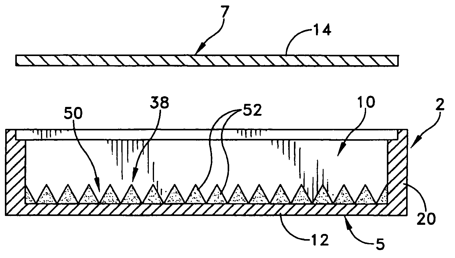
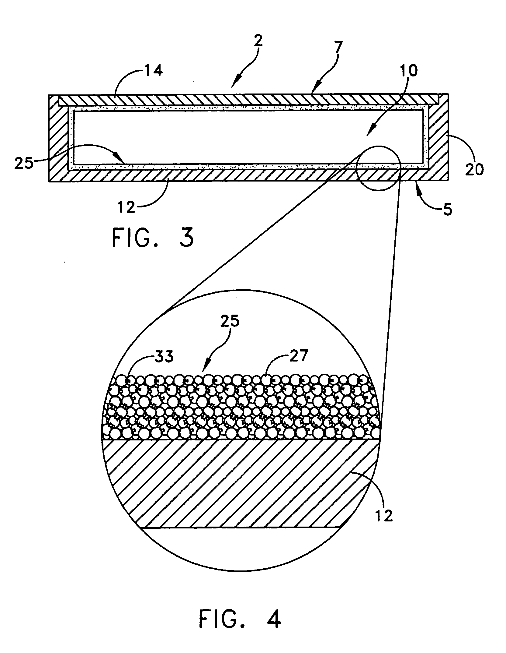
[0009] The present invention provides a capillary structure for a heat transfer device that comprises a plurality of particles joined together by a brazing compound such that fillets of the brazing compound are formed between adjacent ones of the plurality of particles. One or more vapor-vents are defined through the capillary structure so as to provide enhanced vapor escaped passages through the capillary structure. In this way, while a network of capillary passageways are formed between the particles to aid in the transfer of working fluid by capillary action, with the plurality of fillets provided to enhance thermal conduction properties between the plurality of particles so as to greatly improve over all heat transfer efficiency of the device, the one or more vapor vents allow for a minimized pressure drop and therefore a minimized ΔT.

Problems solved by technology

The ability of prior art thermal management technology to get that waste heat out of semiconductor circuits and into the environment, at a reasonable cost, limits the density and clock speed of electronic systems.
As the power to be dissipated from semiconductor devices increases with time, a problem arises: over time the thermal conductivity of the available materials becomes too low to conduct the heat from the semiconductor device to the fins with an acceptably low temperature drop.
The thermal power density emerging from the semiconductor devices will be so high that copper, silver, or even gold based spreader technology will not be adequate.
In addition, the existence of liquid and vapor in equilibrium, under vacuum conditions, results in higher thermal efficiencies.
Although sintered wicks have demonstrated adequate heat transfer characteristics in the prior art, the minute metal-to-metal fused interfaces between particles tend to constrict thermal energy conduction through the wick.
This has limited the usefulness of sintered wicks in the art.
Prior art devices, while adequate for their intended purpose, suffer from the common deficiency, in that they do not fully realize the optimum inherent heat transfer potential available from a given heat pipe.
To date, no one has devised a wick structure for a heat pipe, which is sufficiently simple to produce, and yet provides optimum heat transfer characteristics for the heat pipe in which it is utilized.

Method used


Image

  • Heat transfer device and method of making same
  • Heat transfer device and method of making same
  • Heat transfer device and method of making same

Examples


Embodiment Construction

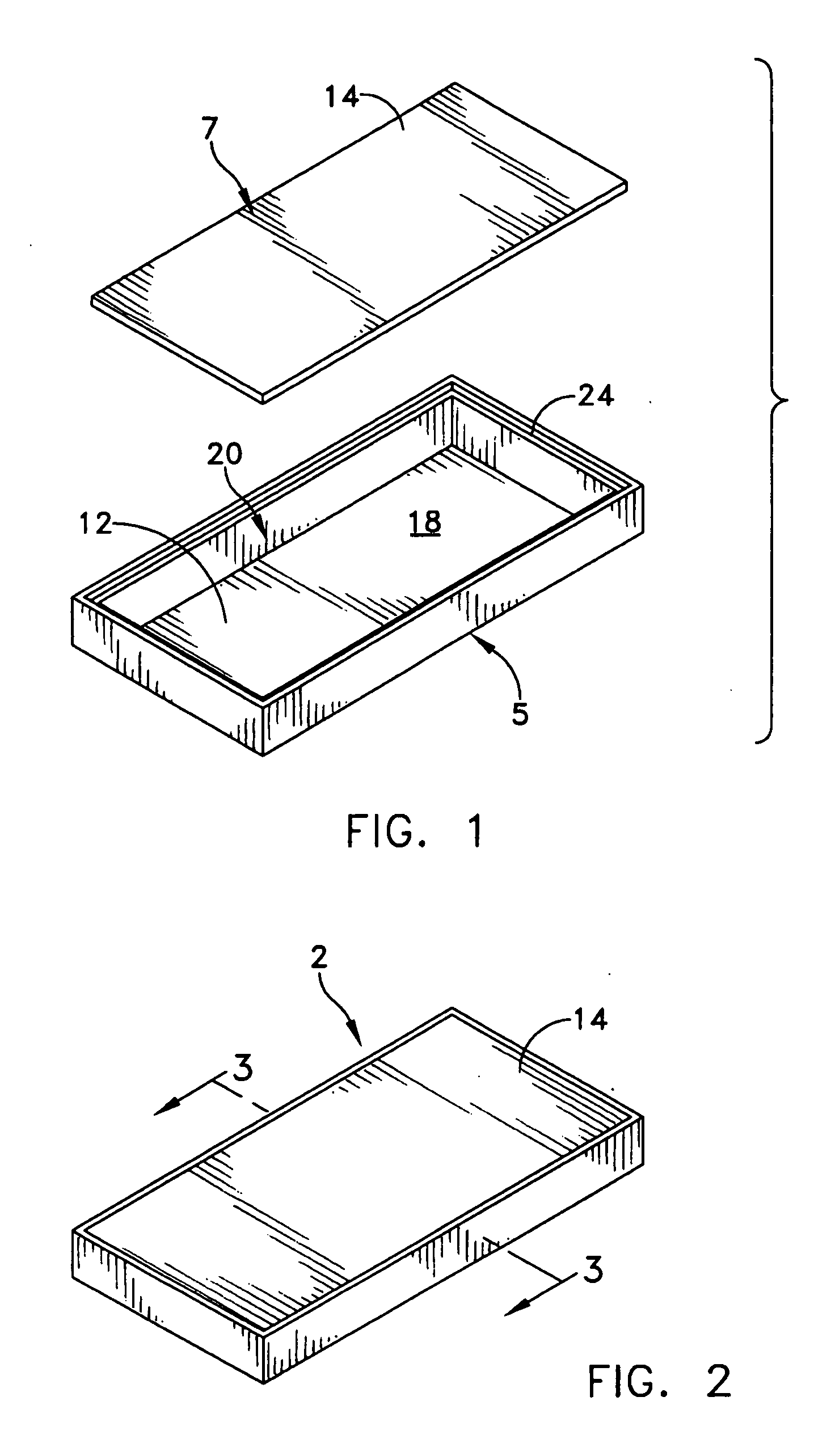
[0046] This description of preferred embodiments is intended to be read in connection with the accompanying drawings, which are to be considered part of the entire written description of this invention. The drawing figures are not necessarily to scale and certain features of the invention may be shown exaggerated in scale or in somewhat schematic form in the interest of clarity and conciseness. In the description, relative terms such as “horizontal,”“vertical,”“up,”“down,”“top” and “bottom” as well as derivatives thereof (e.g., “horizontally,”“downwardly,”“upwardly,” etc.) should be construed to refer to the orientation as then described or as shown in the drawing figure under discussion. These relative terms are for convenience of description and normally are not intended to require a particular orientation. Terms including “inwardly” versus “outwardly,”“longitudinal” versus “lateral” and the like are to be interpreted relative to one another or relative to an axis of elongation, o...


PUM

PropertyMeasurementUnit
Temperatureaaaaaaaaaa
Fractionaaaaaaaaaa
Fractionaaaaaaaaaa

Abstract

A capillary structure for a heat transfer device, such as a heat pipe is provided having a plurality of particles joined together by a brazing compound such that fillets of the brazing compound are formed between adjacent ones of the plurality of particles and one or more vapor vents are defined in the capillary structer. In this way, a network of capillary passageways are formed between the particles and vapor-vents through the capillary structure so as to aid in the transfer of working fluid by capillary action, while the plurality of fillets provide enhanced thermal transfer properties between the plurality of particles so as to greatly improve over all heat transfer efficiency of the device. A method of making the capillary structure according to the invention is also presented.

Description

CROSS-REFERENCE TO RELATED APPLICATIONS [0001] This application is a continuation-in-part of application Ser. No. 10 / 607,337, filed Jun. 26, 2003.FIELD OF THE INVENTION [0002] The present invention generally relates to heat transfer devices that rely upon capillary action as a transport mechanism and, more particularly, to wicking materials for such devices. BACKGROUND OF THE INVENTION [0003] It has been suggested that a computer is a thermodynamic engine that sucks entropy out of data, turns that entropy into heat, and dumps the heat into the environment. The ability of prior art thermal management technology to get that waste heat out of semiconductor circuits and into the environment, at a reasonable cost, limits the density and clock speed of electronic systems. [0004] A typical characteristic of heat transfer devices for electronic systems is that the atmosphere is the final heat sink of choice. Air cooling gives manufacturers access to the broadest market of applications. Anot...

Claims


Application Information

Patent Timeline
IPC IPC(8): B22F7/00B23P6/00F28DF28D15/00F28D15/04F28F7/00F28F13/18H01L23/34H05K7/20
CPCB22F3/1103B22F2998/00F28D15/0233F28D15/046H01L2924/0002H01L23/427F28F2275/04Y10T29/49353B22F2201/013B22F2201/20H01L2924/00
Inventor ROSENFELD, JOHN H.ERNST, DONALD M.
Owner THERMAL
Learn More