
Superfinishing large planetary gear systems

a technology of planetary stage and gear box, which is applied in the direction of gear teeth, manufacturing tools, hoisting equipment, etc., can solve the problems of corrosive seawater environment and/or abrasive particulates, simultaneous loss of electrical generation, and removal of gearbox, etc., to reduce or eliminate lubricant debris

Active Publication Date: 2005-01-20
OSRO GMBH +1
View PDF17 Cites 31 Cited by
  • Summary
  • Abstract
  • Description
  • Claims
  • Application Information

AI Technical Summary

Benefits of technology

Disclosed herein is an improved large planetary gear system used on the input stage of wind turbine power generators. This improved planetary gear system reduces or eliminates lubricant debris traditionally generated from the gear teeth, thereby eliminating an initiating source for bearing failure. To achieve these results, some and preferably all of the gear teeth within the planetary gear system are superfinished using chemically accelerated vibratory finishing to a surface roughness of approximately 0.25 micron or less.
Since the asperity peaks are removed prior to installation, no micro-stresses are introduced such as in the conventional run-in smoothing procedure. In fact, the need for run-in is greatly reduced or completely eliminated. Thus the problems of micropitting and fretting of the gear surfaces are reduced or eliminated. Also, the gears finished with the present invention generate no significant metal debris at start-up or after being in service for long periods, and thus avoids metal debris damaging the bearings. This also allows for longer time between lubrication servicing. Since the smoothing of the surfaces also reduces friction, the gears do not contribute to the typical break-in temperature spike responsible for a reduced life of the lubricant, bearings and seals. Noise and vibration can also be expected to be reduced for two reasons. Firstly, a reduction of friction will effect reduced vibration and noise. Secondly, a reduction in wear means that the transmission error will stay more constant with time, and therefore the noise also will not increase.
Prior to this invention, attempts to improve the durability of wind turbine power generator gearboxes was achieved by surface grinding the gear teeth followed by run-in, whereby the gearbox was operated under varying loads and speeds. Run-in can remove the peak asperities from some of the gear tooth mating surfaces, but also has a number of serious deficiencies as discussed above when compared to the present invention. Accordingly, several objects and advantages of the present invention over the teeth grinding and run-in process applicable to wind turbine power generators having an individual output power capacity of 500 kW and greater are: 1. to provide an improved input planetary stage having the entire teeth flanks superfinished, which reduces or eliminates damaging metal debris generated by the gears during run-in or during actual service; 2. to provide an improved planetary stage with significantly reduced or eliminated metal debris normally generated from the gear teeth, thereby reducing or eliminating an initiating source for bearing failure; 3. to provide a practical and cost-effective method of superfinishing the large hollow wheel gears, especially high geometrical accuracy through-hardened hollow wheels, using chemically accelerated vibratory finishing to a superior surface having a lower Ra, an increased Rmr, and a significant reduction of stress raisers; 4. to provide an improved input planetary stage since now some and preferably all of the gear flanks of any style gear 200 kg and larger can be superfinished to an Ra of 0.25 micron or less while maintaining dimensional tolerances; 5. to provide an improved input planetary stage with significantly reduced micropitting and fretting, which can lead to future macropitting, wear and ultimately to failure of the teeth and bearings; 6. to provide a method which simultaneously superfinishes the drive and coast sides of all the gears and particularly the hollow wheel and sun gear teeth again reducing or eliminating the potential for harmful metal debris; 7. to provide an improved input planetary stage with a significantly reduced temperature spike which can be damaging to the metallurgy, lubricant and seals during the run in or early field operation; 8. to provide an improved input planetary stage with a significantly reduced vibration and / or noise caused by friction and / or tooth profile changes due to wear; 9. to provide an improved input planetary stage having gears with an increased material ratio (Rmr) on the contact teeth surfaces allowing for a greater power density; 10. to provide an improved input planetary stage allowing streamlining or elimination of the run-in process; 11. to provide a process that does not require temper burn inspection after the gears are superfinished; 12. to provide a chemically accelerated vibratory finishing process applicable to all style gears of 200 kg and greater in all types of gear boxes that operate in a boundary lubrication regimes such that superfinishing reduces or eliminates lubricant debris; and 13. to provide an improved large gearbox where some, or preferably, all the gears and / or bearings are superfinished to reduce or eliminate lubricant debris.

Problems solved by technology

These heavy gearboxes, which are mounted atop high towers, often located in remote locations such as on a mountain or offshore, experience severe fluctuations in wind conditions and temperature and are often exposed to a corrosive seawater environment and / or abrasive particulates.
A gearbox failure can require removing the gearbox using mammoth equipment, and rebuilding it back at the manufacturer's facility followed by reinstallation at the remote location.
The concurrent loss of electrical generation is also a costly event unto itself.
Firstly, this will reduce the amount of metal-to-metal contact which produces lubricant debris and which is known to be destructive to gears and bearings.
Honing could have been a consideration for wind turbine gearboxes; except that it is cost prohibitive on such large gears as most honing equipment is limited to processing gears having a diameter of 12 inches or less.
Thus, the lubricant film can be penetrated by peak asperities, and metal-to-metal contact generates metal debris from the gear teeth.
However, a major source of wind turbine gear box failure is failure of the bearings.
Even with run-in achieving the above finishes, metal to metal teeth contact continues on the planetary gear stage teeth and produces lubricant debris, which in turn contributes to the rapid bearing failures.
In contrast, chemically accelerated vibratory superfinishing to a condition of Ra<0.3 micron was thought to be too smooth for large wind turbine generators in that the teeth flanks would have insufficient lubricant retention for operation and tooth failure was predicted.
Thus, it was questionable whether or not superfinishing using chemically accelerated vibratory finishing of the input planetary stage would add any performance value to the gear box.
Only lengthy and costly field testing could provide the answer.
In addition, it was thought by those skilled-in-the-art that the large, heavy gears that make up an input planetary stage of a large wind turbine generator could not be processed in vibratory finishing equipment used in the chemically accelerated vibratory finishing process.
In particular, it was thought that a large hollow wheel gear (annulus gear) weighing from 400 kg to greater than 5000 kg could not be superfinished in a large vibratory bowl.
A person skilled-in-the-art would have predicted that such a massive gear with its relatively small cross sectional area would have immediately sunk to the bottom of the bowl damaging the lining, the gear or both.
In addition, the heavy gear would have been expected to fracture significant quantities of the ceramic media used in the vibratory finishing equipment because of the high pressure exerted upon the media.
Instead of smoothing the critical contact surfaces of the gear teeth to a superfinished condition, these media fragments would have been predicted to damage these surfaces resulting in roughened, gouged and even denting the surfaces, especially nearer the bottom of the bowl where the pressure is greatest.
The anticipated high rate of media attrition from fracturing would also add an unacceptable processing cost as well as causing the problem of clogging and blocking the drains of the processing machine.
Therefore, the vibratory processed hollow wheel gear could end up being out of dimensional tolerance.
It should be mentioned though that turning such a large gear is time consuming and potentially dangerous.
Also, part of the center width of the gear teeth would be processed for twice the finishing time, possibly causing a resultant change in the tooth geometry.
Each of the above predicted shortcomings would have been predicted to make this superfinishing process for large hollow wheel gears commercially impractical and unpredictable.
Therefore, the wind turbine industry could not realize the benefits of this superfinishing process for the input planetary stage of the gear box.
Gas nitriding is expensive, time consuming, and produces a very hard, brittle “white layer” on the teeth surfaces.
However, removal of the white layer by grinding is at great expense and risk to ruining the hollow wheel.
Alternative removal of the white layer by chemical dissolution is a very hazardous and environmentally unfriendly process.
In gas carburizing, due to the significant distortion from the heat treatment process, final grinding of the teeth is required, which is also an expensive process.
Furthermore, after final grinding, the gas carburized hollow wheel requires temper burn inspection, another hazardous and environmentally unfriendly process.
However, duplicating actual service conditions on a test rig is not only virtually impossible, but is also impractical as well due to equipment, time and cost constraints.
Unfortunately, even during run-in, this metal debris can initiate serious damage to the bearings and gear contact surfaces before collection in a filter.
These fine particles still are capable of causing surface damage, particularly to the gear box bearings.
Also, no matter how thoroughly or carefully the run-in procedure is conducted, this process leaves microscopic material distress (stress raisers) on the gear teeth contact regions due to the high stresses created to mechanically shear, fracture or elastically deform the peak asperities.
Micropitting by itself is another source of metal debris which can cause further damage to the bearings and gear contact surfaces since the metal debris is not immediately or completely trapped by the filtration system.
Whenever severe wear occurs, the gear tooth profile is changed leading to increased vibration and noise which places an elevated stress on the gear box system.
Additionally, run-in procedures typically only smooth the drive side of the hollow wheel and sun gear while leaving the coast sides of these gear teeth as machined.
During adverse operating conditions such as strong gusts of wind or turbine braking, coast side loading can be high enough to produce asperity contact and contribute to harmful metal debris.
Again, it needs to be emphasized that the industry has failed to give guidance on the actual optimum surface finish, or on the method of generating such optimum surfaces to improve gearbox durability.

Method used


Image

  • Superfinishing large planetary gear systems
  • Superfinishing large planetary gear systems
  • Superfinishing large planetary gear systems

Examples


Embodiment Construction

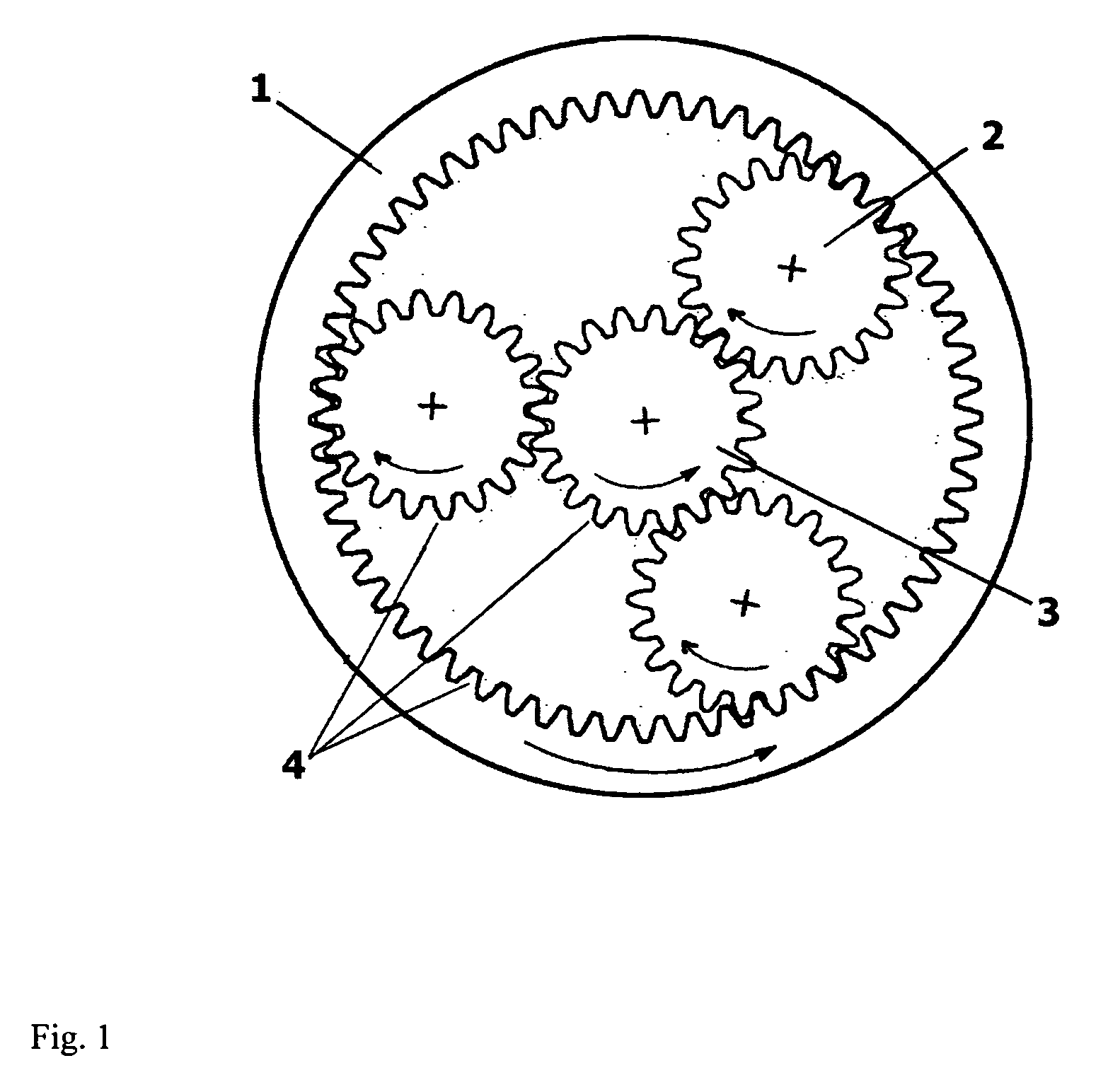
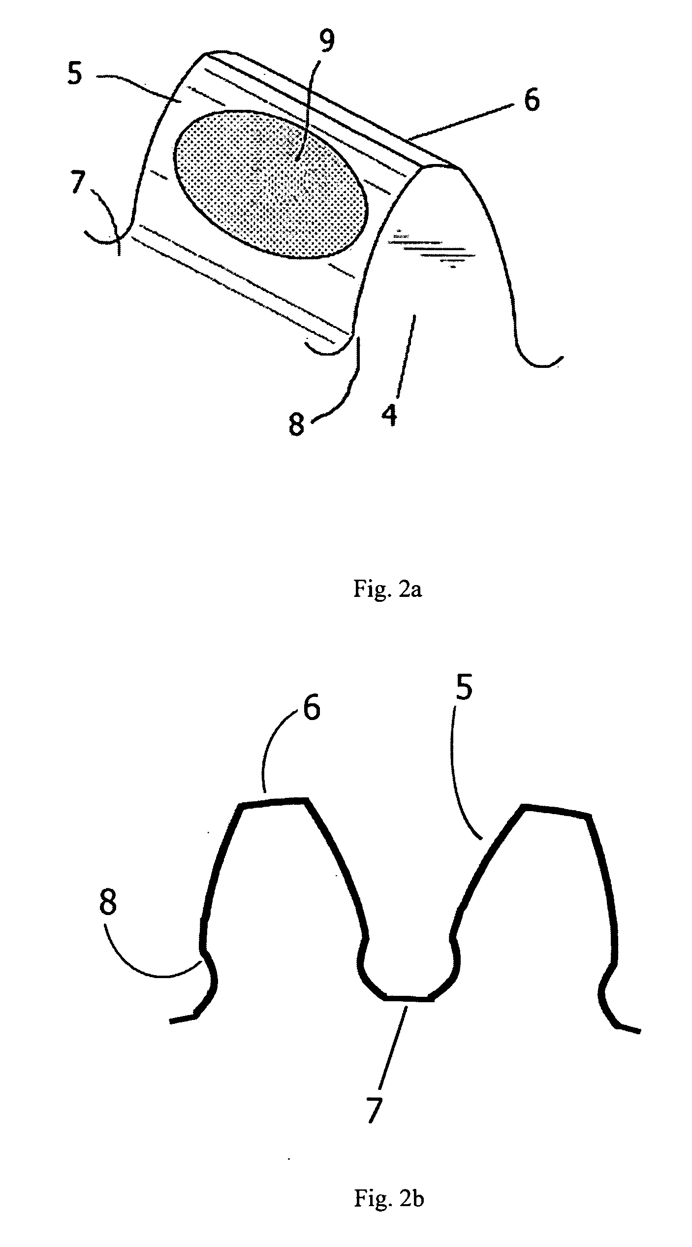
FIG. 1 is a drawing of an input planetary stage typically used in wind turbine gearboxes. It consists of a hollow wheel gear (1), two or more planet gears (2), and a sun gear (3). The teeth (4) of each gear are to be superfinished. FIG. 2a is a 3-dimensional view of a single gear tooth (4) and FIG. 2b shows a 2-dimensional cross section of two gear teeth (4). The gear tooth (4) consists of the flank (5), which is the working or contacting side of the gear tooth, the top land (6), which is the top surface of the gear tooth, the bottom land (7), which is the surface at the bottom of the space between adjacent teeth, and the root fillet (8), which is the rounded portion at the base of the gear tooth between the tooth flank (5) and the bottom land (7). The most critical area is the tooth contact pattern (9), which is the surface area of a gear tooth which has been in contact with its mate when the gears are in operation. In the present invention, one or more of the planetary gears of a ...


PUM

PropertyMeasurementUnit
surface roughnessaaaaaaaaaa
diametersaaaaaaaaaa
diametersaaaaaaaaaa

Abstract

Disclosed herein is a new improved large planetary gear system used on the input stage of wind turbine power generators. This improved planetary gear system reduces or eliminates lubricant debris traditionally generated from the gear teeth, thereby eliminating an initiating source for bearing failure. To achieve these results, some and preferably all of the gear teeth within the planetary gear system are superfinished using chemically accelerated vibratory finishing to a surface roughness of approximately 0.25 micron or less. Several objects and advantages of the invention are to provide a gearbox with reduced metal debris, improved bearing life, reduced wear, reduced vibro-frictional noise, improved contact fatigue, improved fretting resistance, improved lubrication, to simplify the run-in process, and to enhance the durability and efficiency of the gearbox.

Description

BACKGROUND OF THE INVENTION This invention relates to a new improved input planetary stage for a large gear box. The input planetary stage cited in this invention is for a wind turbine power generator having an output power capacity rating of 500 kW and greater. Wind turbine power generators are considered one of the most cost effective and environmentally friendly methods of generating electricity. Individual wind turbines are currently being designed and built for electrical power generation in excess of 5 MW. A key component of most wind turbines are their gearboxes, which are subjected to varying high loading at low speeds, and have design lifetimes of 20 years. Anything that will give these gearboxes more durability and efficiency is highly coveted by wind turbine manufacturers and operators. Modern large wind turbine generators (500 kW and greater) are massive devices commonly using large planetary gear systems as the input stage. These heavy gearboxes, which are mounted at...

Claims


Application Information

Patent Timeline
Patent Type & Authority Applications(United States)
IPC IPC(8): B24B31/00F16H55/06F16H57/00F16H57/04F16H57/08
CPCB24B31/00F16H55/06F16H57/0006Y10T29/49467F16H57/0463F16H57/08Y02B10/30F16H57/04B24B31/073B23F19/00B24B31/06
Inventor MICHAUD, MARKSUMMERS, EDWARD DAVID
Owner OSRO GMBH
Learn More