However, such methods are costly.
However, with this method, it is not easy to fix the particles onto the
substrate surface or to form a single layer film thereof on the surface of the substrate and to control the surface reflectance.
The aforementioned transparent films, however, are not sufficient in scratch resistance, being liable to be scratched at the surface to become inferior in the transparency or the antireflection property of substrate.
However, in the aforementioned electroconductive coating films formed on substrate, the fine
metal particles contained therein can be oxidized, can grow to larger particles by
metal ionization, or can be corroded.
Thereby, the electroconductivity or light
transmittance of the coating film may be decreased, which lowers the. reliability of the display apparatus.
Further, the electroconductive
oxide particles and fine
metal particles contained in the electroconductive coating film have high refractivity, which causes reflection of light, disadvantageously.
On the other hand, when a conventional transparent coating film containing a matrix composed of silica or the like is formed on the electroconductive film surface, the density of the electroconductive film is liable to become nonuniform owing to the difference in the shrinkage degree between the transparent film and the electroconductive film.
Thereby, the locally failure of
electric contact between the electroconductive fine particles may be caused.
As a result in insufficient overall electroconductivity of the film may be caused.
Furthermore, in the heating treatment, the transparent coating film is not sufficiently compactified to become porous and to form cracks and voids, which may promote penetration of
moisture and a chemical such as acids and alkalis, disadvantageously.
The acid or alkali having penetrated into the transparent coating film may react with the surface of the substrate to lower the refractivity, or may react with the fine particles of the metal or the like in the formed electroconductive coating film, when it is employed, to lower the
chemical resistance of the coating film and to decrease the antistatic property and electromagnetic wave
shielding effect of the electroconductive film, disadvantageously.
This makes the visual feeling of the image reflection (
mirror reflection) stronger, and the coloration of the reflected light cannot readily be suppressed.
Therefore, such a film-coated substrate used, for example, as a front face plate of a
cathode ray tube can lower the resolution of the displayed image.
On the other hand, the fine metal particles having the average particle
diameter of less than 1 nm tends to increase the surface resistance of the particulate layer greatly, which may make difficult to achieve the object of the present invention.
The electroconductive film-forming liquid containing the fine metal particles at a concentration lower then 0.05% by weight tends to give a smaller thickness of the produced film resulting in insufficient electroconductivity of the film.
On the other hand, at a fine metal particles concentration of higher than 5% by weight, the coating liquid tends to produce a larger thickness of the film to lower the light
transmittance to deteriorate the transparency and impair the appearance of the layer.
With the electroconductive
inorganic particles contained in an amount of more than 4 parts by weight, the electroconductivity may be lower not to give sufficient electromagnetic wave
shielding effect undesirably because the portion of the fine metal particles in electroconductive film is decrease.
At the concentration of lower than 0.1% by weight of the fine electroconductive particles, the resulting film tends to be thinner, which may give insufficient antistatic property.
On the other hand, at the concentration of higher than 10% by weight of the fine electroconductive particles, the resulting film tends to be thicker to lower the light
transmittance to decrease the transparency and impair the appearance of the film.
With the amount of less than 0.005 part by weight, the organic stabilizer tend not to give sufficient dispersibility, whereas with the amount of more than 0.5 part by weight, it may lower the electroconductivity.
The heat treatment at a temperature lower than 100.degree. C. does not necessarily cure the matrix component sufficiently.
The porous material of
molar ratio MO.sub.x / SiO.sub.2 of less than 0.0001 cannot readily be prepared, and even if it could be obtained, it would not give lower
refractive index.
However, no control is necessary for controlling the pH in a certain range.
This protecting silica film formed in this step is porous and thin, so that it does not prevent the removal of the non-silica
inorganic compound from the porous material precursor particles.
An excessive amount of the silica source results in an excessive thickness of the protecting silica film, which may render difficult the removal of the non-silica
inorganic compound from the porous material precursor particles.
The heat treatment at a temperature lower than 80.degree. C. may cause clogging of the fine pore of the silica shell without compactifying the shell layer, of may require much time for the treatment.
On the other hand, whereas the heat treatment at 300.degree. C. or higher for a long time may compactify the inner porous material-constituting compound (porous matter), not achieving the low refractivity undesirably.
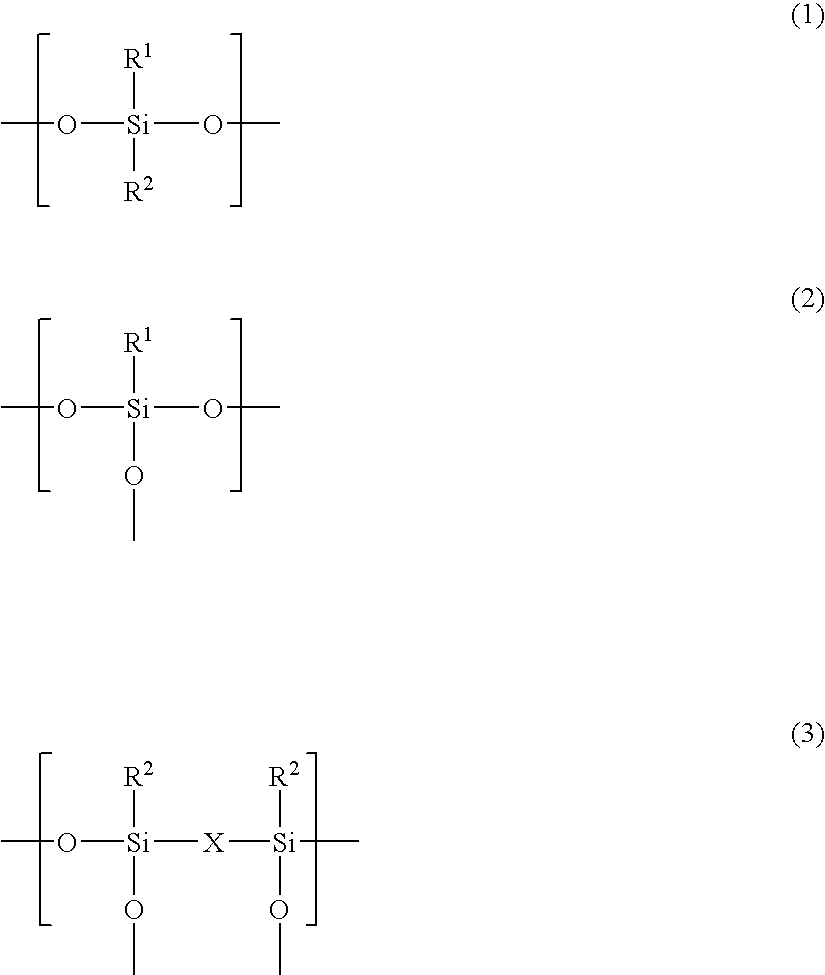
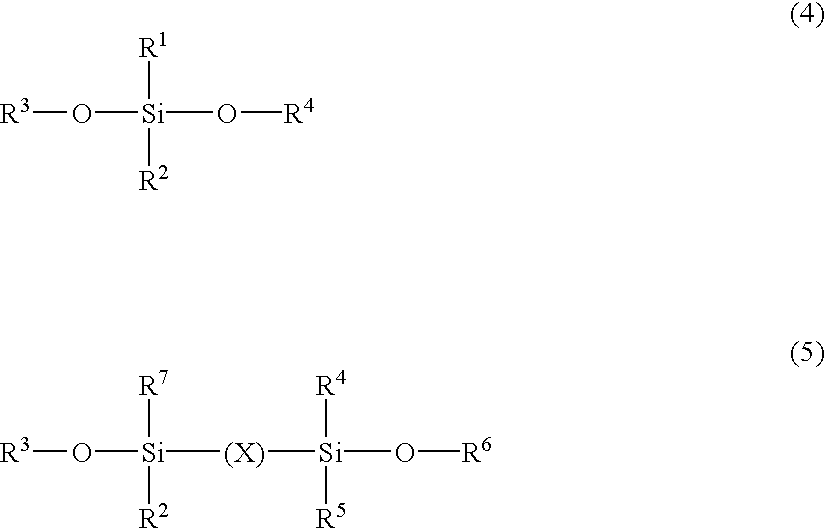
At a content of less than 0.1% by weight of the
fluorine-substituted
alkyl-containing
silicone represented by the above Formulas (1) to (3) in the matrix in terms of SiO.sub.2, the formed transparent coating film may not have a sufficient slipping property and may not have sufficient scratch resistance.
Therefore, increase of the other component will increase the shrinkage of the transparent coating film, which may cause warpage of the substrate in the heat treatment (curing) of the transparent coating film.
In case of underlying the electroconductive film, exfoliation of the electroconductive layer or local
electric contact failure may be caused or by the difference in shrinkage between films.
As a result, total electroconductivity of film becomes insufficient.
The increased shrinkage compactifies the film excessively, which may prevent the pore formation to weaken the effect of decrease of the
refractive index of the transparent coating film.
Further, the less content of the
fluorine compound of a low
electron density tends to render the decrease of the refractive index of the transparent film insufficient.
Further the less content of the fluorine-substituted
alkyl-containing
silicone component may make the hydrophobicity of the transparent film insufficient, resulting low chemical resistance.
At a content of higher than 70% by weight of the fluorine-substituted alkyl-containing silicone represented by the above Formulas (1) to (3) in the matrix in terms of SiO.sub.2, the formed transparent coating film may become excessively porous to cause drop of the film strength, drop of strengths such as the rubber eraser strength and scratch strength, and insufficient adhesiveness to the substrate or the electroconductive layer.
The silica precursor having a molecular weight of lower than 500 in terms of
polystyrene may remain unhydrolyzed in the coating liquid, which may cause nonuniform application of the transparent coating film forming liquid on the electroconductive layer, or less adhesion of the transparent coating film to the electroconductive film even if it can be uniformly applied.
This shrinkage may cause warpage of the substrate in the heat treatment (curing) of the transparent coating film.
In case of underlying the electroconductive film, exfoliation of the electroconductive layer or local
electric contact failure may be caused or by the difference in shrinkage between films.
As a result, total electroconductivity of film becomes insufficient.
The increased shrinkage compactifies the transparent film excessively, which may lowers the
porosity of the film to weaken the effect of decrease of the refractive index of the transparent coating film.
Further the less content of the fluorine-substituted alkyl-containing silicone precursor may decrease the hydrophobicity of the transparent film, resulting in low chemical resistance.
With the fluorine-substituted alkyl-containing silicone precursor in a mixing amount of more than 70% by weight, the formed transparent coating film may become excessively porous to cause drop of the film strength, and insufficient adhesiveness to the substrate or the underlying electroconductive layer.
At the concentration of the inorganic compound particles of lower than 0.05% by weight in the transparent film-forming liquid, the formed transparent coating film has insufficient anti-reflection property owing to insufficient amount of the inorganic compound particles, whereas at the concentration higher than 3% by weight, cracks may be formed or the film strength may be lowered.
At the concentration of the matrix precursor of lower than 0.05% by weight in terms of the
oxide in the coating liquid, the formed film is insufficient in
water resistance and anti-reflection property owing to insufficient thickness of the formed film.
At such a concentration of the matrix precursor, a sufficient thickness of the layer may not be obtained by one application, and may give nonuniform thickness of the film by repeated application.
On the other hand, at the concentration of the matrix precursor of higher than 10% by weight in terms of the
oxide, cracks may be caused or the film strength may be lower, or the anti-reflection property may be insufficient owing to the larger thickness of the film.
The transparent coating film of the thickness of less than 50 nm may be inferior in film strength,
water resistance, anti-reflection property, and so forth, whereas the transparent film of the thickness of more than 300 nm may cause
cracking therein, or have lower film strength, or insufficient anti-reflection property owing to the excessive film thickness.
