
Optical and optoelectronic assembly and method for the production thereof

a production method and technology of optical or optoelectronic components, applied in semiconductor lasers, additive manufacturing processes, semiconductor/solid-state device details, etc., can solve the problems of poor heat transfer, limited structural design of the cooler, and the mounting surface of the component is in electrical contact with the heat sink, etc., to achieve a simple and cost-effective production method, the effect of reducing the cost of cooling

Active Publication Date: 2020-08-11
JENOPTIK OPTICAL SYST
View PDF38 Cites 2 Cited by
  • Summary
  • Abstract
  • Description
  • Claims
  • Application Information

AI Technical Summary

Benefits of technology

This method enables cost-effective, efficient cooling of optical or optoelectronic components with reduced thermomechanical stresses and improved heat transfer, allowing for parallel production of assemblies with enhanced reliability and longevity.

Problems solved by technology

What is disadvantageous is that the mounting surface for the component is in electrical contact with the heat sink.
If it is necessary for the component to be electrically insulated from the heat sink, an insulating intermediate layer has to be provided, which has the disadvantage that the heat transfer is poorer owing to additional interface layers.
What is disadvantageous is that there are limitations in the structural design of the coolers, and the production of the coolers is costly and complex.
What is disadvantageous is that the cooler can have a leak rate, and there is a lack of electrical insulation.
In this case, the laser disk can become wet and, moreover, the coolant jet can have an abrasive effect, which can adversely affect the lifetime.
What is disadvantageous is that the power electronic component is subjected to the loads during the process of producing the cooler structure.
What is disadvantageous is that there is the risk of the laser source being damaged in the process.

Method used


Image

  • Optical and optoelectronic assembly and method for the production thereof
  • Optical and optoelectronic assembly and method for the production thereof
  • Optical and optoelectronic assembly and method for the production thereof

Examples


Embodiment Construction

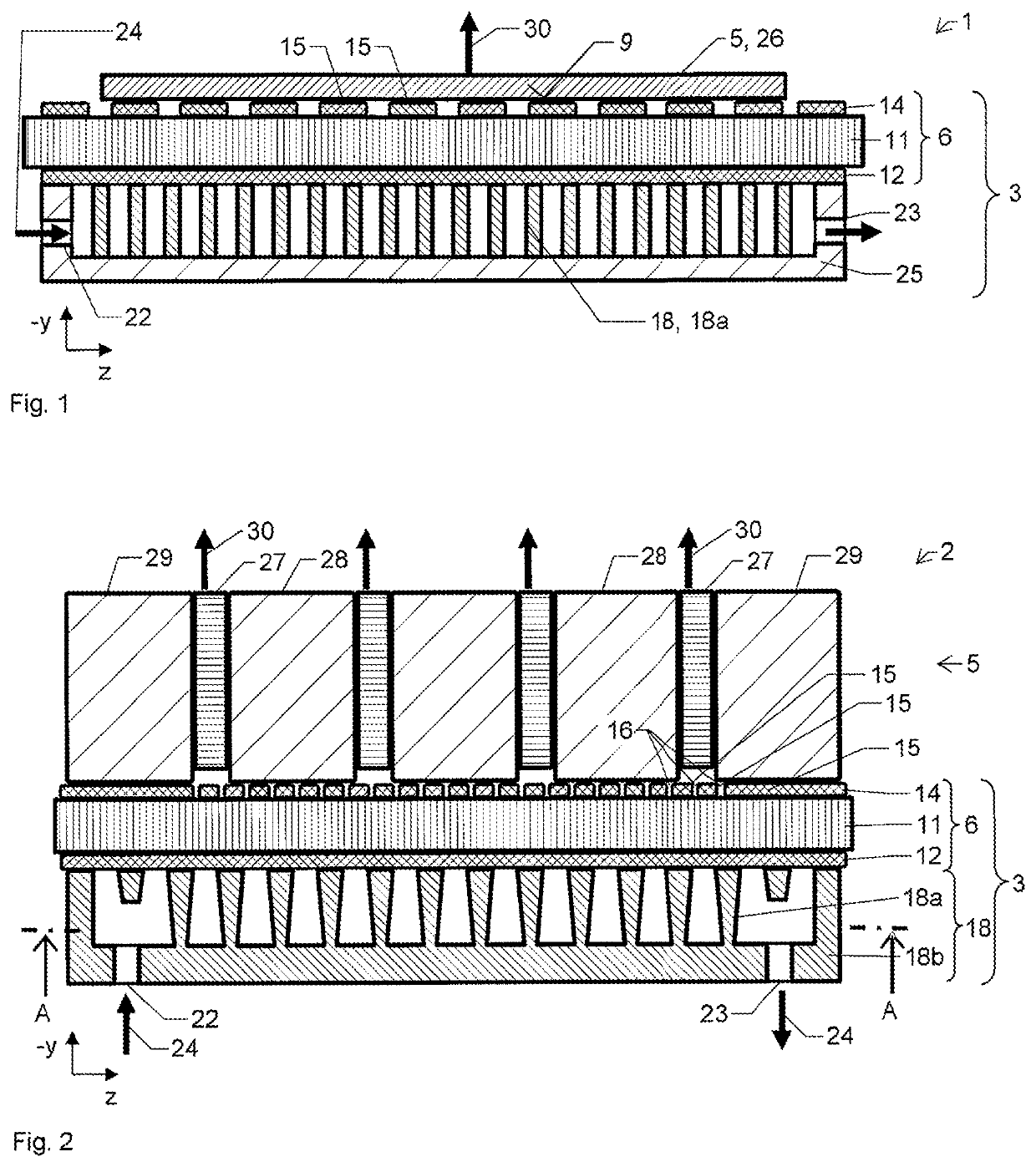
[0076]FIG. 1 shows a second exemplary embodiment of an optical assembly 1 in a yz section. The assembly comprises a cooler 3 and an optical component 5, which is present as a laser disk 26. During operation, a laser radiation 30 is emitted in the −y direction. In order to dissipate the waste heat from the laser disk 26, a coolant flow 24 is used. Water, for example, is considered as coolant. The cooler 3 comprises a composite plate 6, a cooler structure 18, which is present here as an inner cooler structure 18a, and also a hood 25, which delimits the coolant flow from the surroundings. A coolant inlet 22 and a coolant outlet 23 are incorporated into the hood 25. The composite plate 6 comprises a first nonmetallic layer 11, a first metallic layer 12 and a second metallic layer 14, which is subdivided into a plurality of second regions 15. The second metallic layer 14 has a mounting surface 9, to which the laser disk 26 is secured. In this case, the laser disk 26 covers a plurality of...


PUM

PropertyMeasurementUnit
thickaaaaaaaaaa
thicknessaaaaaaaaaa
thicknessaaaaaaaaaa

Abstract

The invention relates to the production of an optical or optoelectronic assembly (1, 2) comprising an active component (5) and a cooler (3). The cooler (3) is produced by means of a 3D printing method on a composite plate (6).

Description

[0001]This nonprovisional application is a National Stage of International Application No. PCT / EP2017 / 074223, which was filed on Sep. 25, 2017, and which claims priority to German Patent Application No. 10 2016 218 522.5, which was filed in Germany on Sep. 27, 2016, and which are both herein incorporated by reference.BACKGROUND OF THE INVENTIONField of the Invention[0002]The present invention relates to the production of an optical or optoelectronic assembly using a 3D printing method. The assembly comprises an optical or optoelectronic component, which is intended to be cooled during operation, and a cooler.Description of the Background Art[0003]EP1672690A1 discloses a microchannel cooler for a laser bar, and the production of same by selective laser melting of a metal powder. What is disadvantageous is that the mounting surface for the component is in electrical contact with the heat sink. If it is necessary for the component to be electrically insulated from the heat sink, an ins...

Claims


Application Information

Patent Timeline
Patent Type & Authority Patents(United States)
IPC IPC(8): H01S5/024B33Y80/00H01L33/64H01S5/40B33Y10/00B33Y70/00B22F3/105H01L21/48
CPCH01S5/02476B33Y80/00H01L33/644H01S5/4025H01L33/648B22F3/1055H01S5/02423B33Y10/00H01L2933/0075H01L21/4871B33Y70/00H01S5/4018H01L23/473H01S5/4043B22F5/10B22F7/08C22C26/00H05K3/0061B29C64/153B29C64/188H01S5/405Y02P10/25H01S5/0237B22F10/28B22F12/41
Inventor WOLF, JUERGENHIRSCH, ANNELIES
Owner JENOPTIK OPTICAL SYST
Learn More