
Bipolar plate structure having optimized gas flow channels

a technology of bipolar plates and gas flow channels, which is applied in the direction of fuel cells, fuel cell details, and electrochemical generators, can solve the problems of complex manufacturing process, time-consuming and time-consuming, and facilitate the miniaturization of fuel cells, so as to improve the electricity production efficiency of fuel cells, low thickness, and low weight

Active Publication Date: 2020-05-05
HWANG JENN JIANG
View PDF3 Cites 0 Cited by
  • Summary
  • Abstract
  • Description
  • Claims
  • Application Information

AI Technical Summary

Benefits of technology

The present invention provides a bipolar plate structure with optimized gas flow channels for fuel cells that has a metal bipolar plate with innovative design of gas flow channels to allow for even distribution of fuel gas, oxidant, coolant, and the like. The flow paths have been molded from a stainless steel plate and surface modifications have been made to improve corrosion resistance and mechanical strength. The design also allows for maximization of coolant flow field to meet cooling requirements and higher power density related to weight. Overall, this structure improves corrosion resistance, mechanical strength, and increases the life of the fuel cell.

Problems solved by technology

There are many problems of electrode plate material, flow field structure or processing cost of the fuel cell to be solved.
For the electrode plate formed of the graphite and the composite carbon material, it has the advantages of conductivity and corrosion resistance, but its manufacturing process is complicated and time consuming.
Moreover, the electrode plate formed of the graphite and the composite carbon material has a thickness of not less than 3 mm, which is not conducive to the miniaturization of the fuel cells.
However, this kind of fuel cell made from the metal electrode plates has lower electricity production efficiency due to a low transport capacity of flow ducts on the metal electrode plates.
However, the abovementioned structure having the plurality of bends on the gas flow channel surface may increase resistance to gas flow when the fuel gas (e.g. hydrogen), oxidant (e.g. oxygen) and the like flows in the flow channels for reaction and thus reduces electricity production efficiency.

Method used


Image

  • Bipolar plate structure having optimized gas flow channels
  • Bipolar plate structure having optimized gas flow channels
  • Bipolar plate structure having optimized gas flow channels

Examples


Embodiment Construction

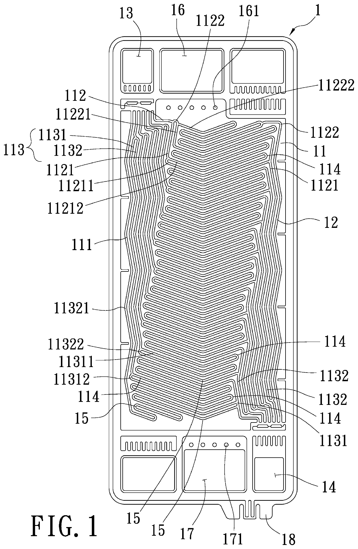
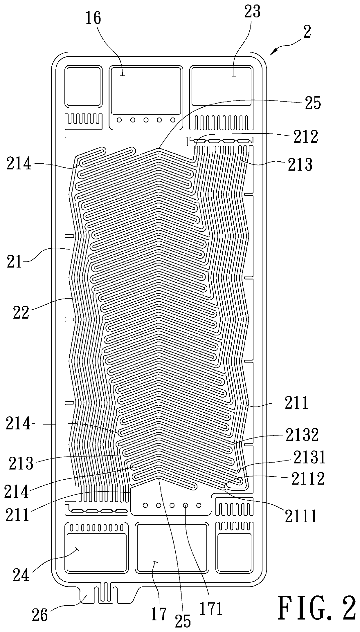
[0034]Hereinafter, an exemplary embodiment of the present invention will be described in detail with reference to the accompanying drawings.

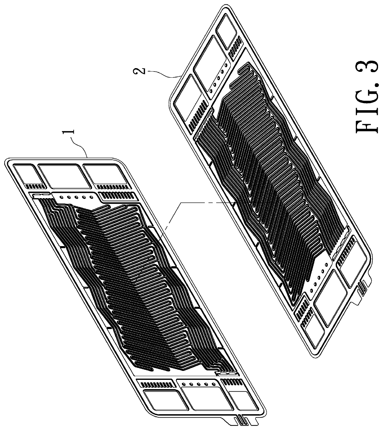
[0035]The main function of the electrode plates of a fuel cell is to guide reaction gases such as the fuel gas (e.g. hydrogen) and the oxidant (e.g. oxygen) respectively from a hydrogen entry end of an anode electrode plate and an oxygen entry end of the cathode electrode plate to the flow paths and to guide the coolant from the coolant inlets to the flow paths located on the back sides of the anode electrode plate and the cathode electrode plate. By an innovative design of the gas flow paths, the hydrogen and the oxygen are distributed on a reaction area, and the unused reaction gas and coolant are guided to flow out of the flow paths. The anode electrode plate and the cathode electrode plate are respectively disposed on two sides of a membrane electrode assembly. The principle of operation is that the fuel gas (e.g. hydrogen) and the oxidant (...


PUM

PropertyMeasurementUnit
thicknessaaaaaaaaaa
thicknessaaaaaaaaaa
thicknessaaaaaaaaaa

Abstract

A bipolar plate structure having optimized gas flow channels is disclosed herein. It mainly comprises an anode electrode plate having a gas flow path plane molded by stamping processing and a plurality of zigzag meandering grooves formed on the gas flow path plane for a flow of hydrogen; and a cathode electrode plate having a gas flow path plane molded by stamping processing and a plurality of zigzag meandering grooves formed on the gas flow path plane for a flow of oxygen.

Description

BACKGROUND OF THE INVENTION[0001]1. Field of the Invention[0002]The present invention relates to a bipolar plate structure having optimized gas flow channels, especially for a metal bipolar plate of a fuel cell to allow the fuel gas, oxidant, coolant and the like to be evenly distributed on a specific gas flow path plane, so as to improve corrosion resistance and mechanical strength of the bipolar plate and increase the life of the fuel cell.[0003]2. Description of Related Art[0004]As the traditional petrochemical energy has been gradually depleted and the use of petrochemical energy makes a significant impact on the ecological environment, governments around the world have turned to the development of low-pollution and energy-efficient energy sources. Among the new developed energy sources including solar cells, biochemical energy, fuel cells, and the like, the fuel cells have attracted attention due to having a high power generation efficiency of about 60% and low pollution.[0005]...

Claims


Application Information

Patent Timeline
Patent Type & Authority Patents(United States)
IPC IPC(8): H01M8/0258H01M8/0267H01M8/04014H01M8/0206H01M8/0263H01M8/1018H01M8/04537
CPCH01M8/04014H01M8/0258H01M8/0206H01M8/0263H01M8/0267H01M8/04582H01M8/04552H01M2008/1095H01M8/026Y02E60/50
Inventor HWANG, JENN-JIANGWENG, WEI-HONGWANG, SUNG-ENLIN, CHIH-HONG
Owner HWANG JENN JIANG
Learn More