
Device and method for forming a composite panel from a thermoplastic matrix

a thermoplastic matrix and composite blank technology, applied in the field of apparatus and method for stamping thermoplastic matrix composite blanks, can solve the problems of high price, fiber undulation, and the prior art device proves to be poorly reliable in the framework of industrial production, and achieves the effect of simple and economical implementation

Active Publication Date: 2020-05-05
DAHER AEROSPACE
View PDF4 Cites 0 Cited by
  • Summary
  • Abstract
  • Description
  • Claims
  • Application Information

AI Technical Summary

Benefits of technology

The invention relates to a method for heating and transferring a polymer blank during a stamping process. The method is efficient in keeping the blank cool and prevents deformation, which improves the quality of the parts obtained. The heat sink, consisting of a cleat holding the locator, provides cooling to the blank face that touches it and reduces its absorption of infrared radiation. The guiding hole of the blank allows for easy positioning without impeding its sliding in the stamping direction. Overall, the method of the invention enhances the mechanical quality of the parts obtained during the stamping process.

Problems solved by technology

This method of shaping is satisfactory, but presents some drawbacks related notably to the use of the polyimide film.
Actually, being stamped with the blank, said film is not reusable, although being of a high price when the polymer constituting the composite matrix exhibits a high melting point, for example PEEK.
In addition, as the film is not plastically deformable at the stamping temperature, it tends to wrinkle during this operation, the wrinkles being printed in the piece and causing fibers undulations.
This device of the prior art proves to be poorly reliable in the framework of an industrial production.
In fact, the loss of the mechanical properties of the blank during heating frequently leads to its falling from the frame and even when the blank is further held by the locator, the bore tends to deform around said locator, leading to defects such as resin squeezing, pinching or undulations of the fibers; these defects, considering the continuous nature of the fibers, are likely to propagate at remote distances from the locator.
During stamping, if the blank does not succeed in escaping from the locator, the latter causes tearing and hinders the interlaminar slipping, thus leading to defects.
Such a thin sheet, non-reinforced by fibers, tends to shrink during heating.
Such a method cannot be used in the case of a continuous fibers reinforced composite blank, the blank holder preventing the interlaminar slipping that is required for the forming.

Method used


Image

  • Device and method for forming a composite panel from a thermoplastic matrix
  • Device and method for forming a composite panel from a thermoplastic matrix
  • Device and method for forming a composite panel from a thermoplastic matrix

Examples


Embodiment Construction

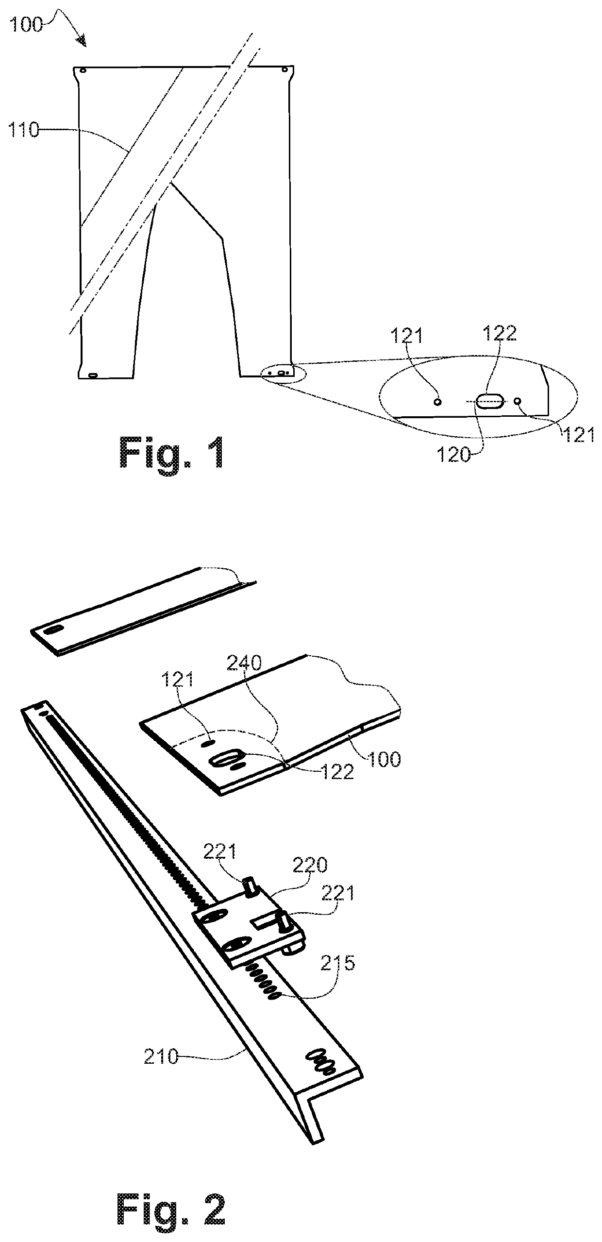
[0051]FIG. 1, according to an exemplary embodiment, the apparatus of the invention includes a consolidated machined composite blank (100). The blank (100) is made of one or several stratified layers including continuous fibrous reinforcements (110), meaning that they extend from one edge to another of said blank (100), in a matrix made of a thermoplastic polymer. This blank is called machined, meaning that prior to its forming by stamping, it is routed according to a defined contour. Said routing is performed by any method known from the prior art, especially, but not exclusively, by means of a cutting tool or using a high pressure water jet. These routing operations include the cut out of holes (121, 122) intended to receive positioning elements of said blank (100) according to a tooling repository.

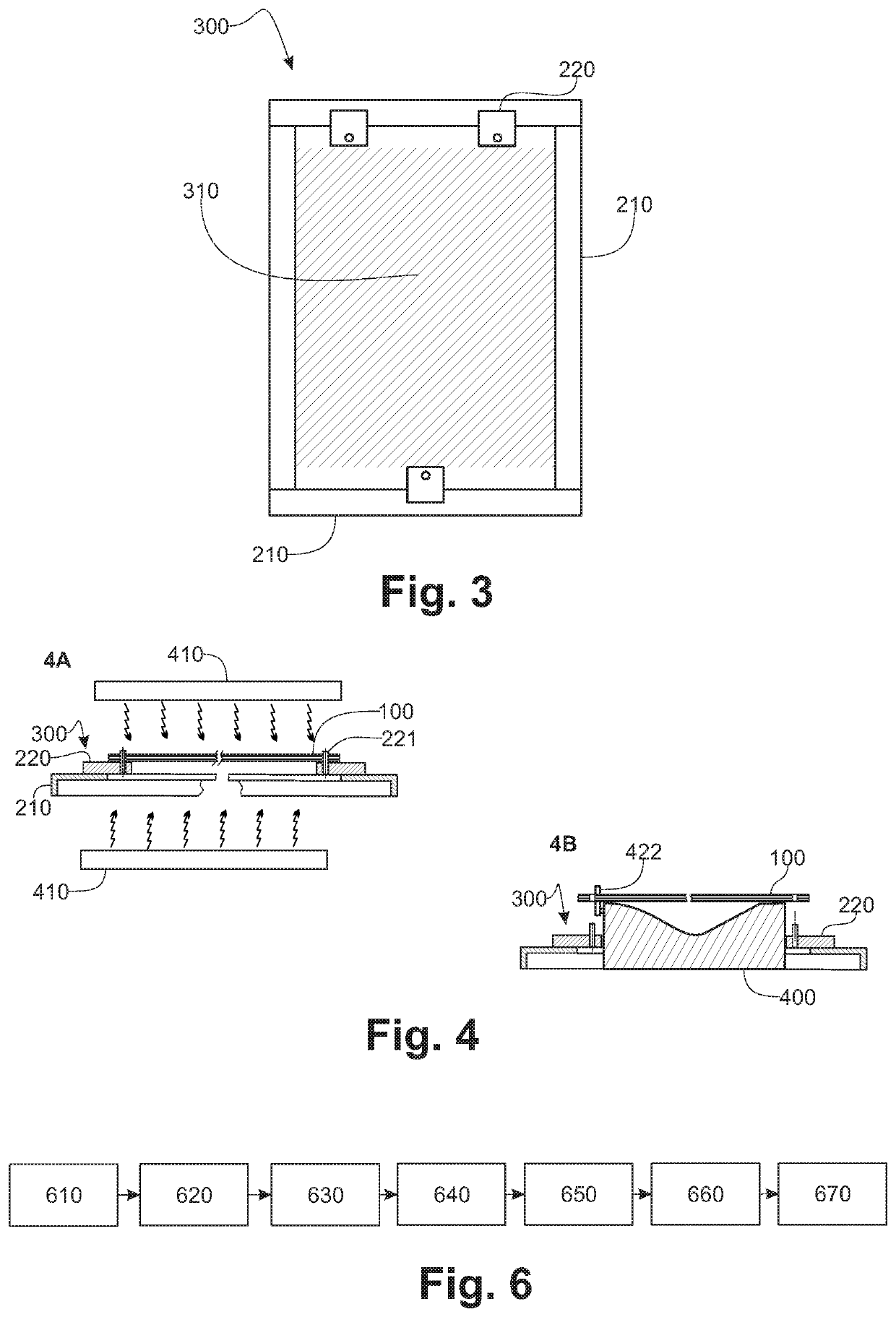
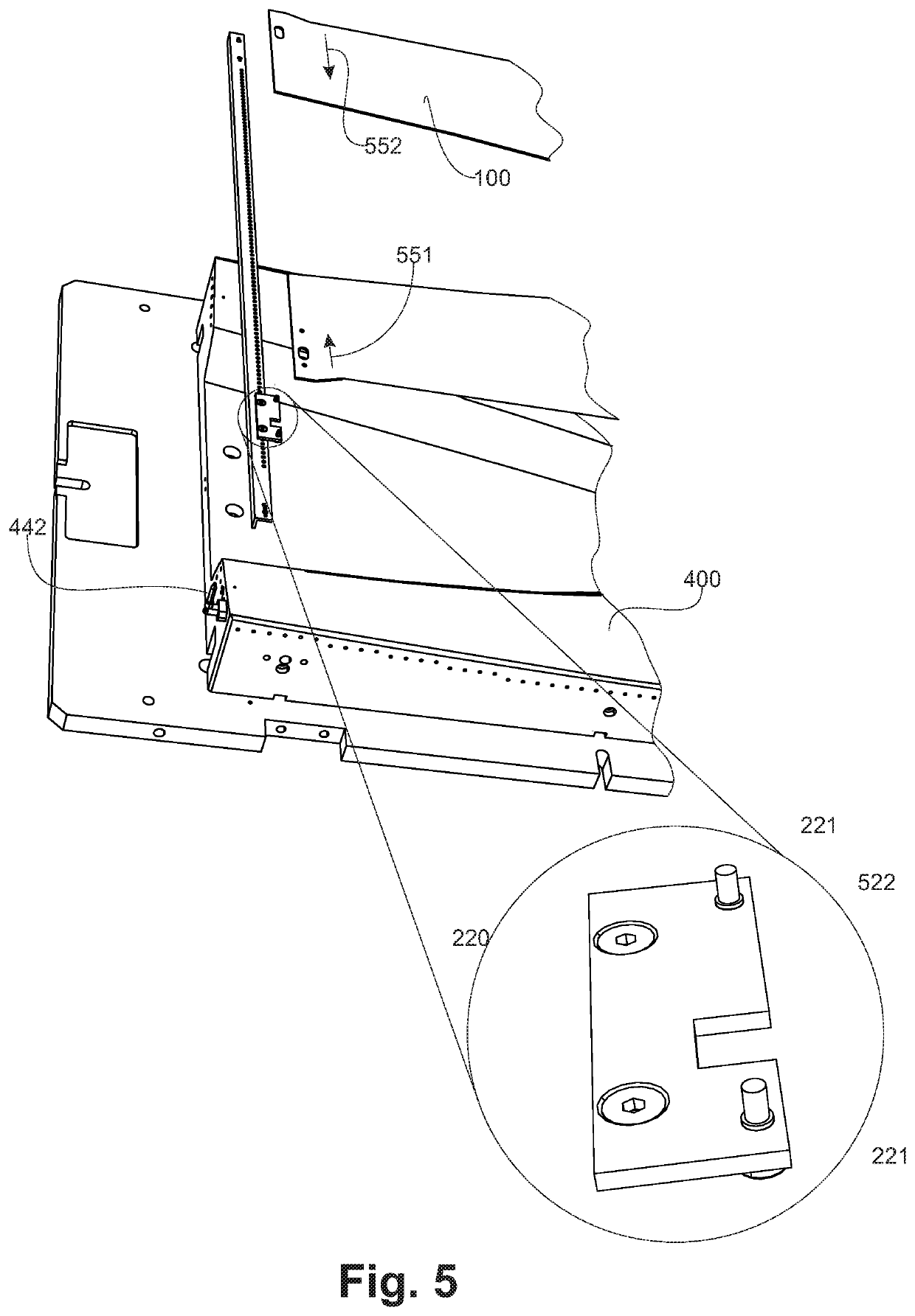
[0052]FIG. 2, for its transfer from the heating station to the stamping tooling, the blank (100) is held by a frame which, according to this exemplary embodiment is made of an assembly o...


PUM

PropertyMeasurementUnit
thermal diffusivityaaaaaaaaaa
perimeteraaaaaaaaaa
viscosityaaaaaaaaaa

Abstract

An apparatus and method for stamping a thermoplastic matrix composite blank, in view of heating and stamping the blank. The apparatus includes a machined blank and a frame. A plurality of cleats are fixed on the frame, extend towards the interior of the frame. The cleats delimit an internal opening surface of the frame, free from any obstacle. A locator is linked with a cleat and configured to cooperate with a hole machined in the blank. A heat sink is located near the locator and configured to maintain locally the blank temperature under the melting temperature of the polymer constituting the matrix, during the heating and transfer of the blank.

Description

RELATED APPLICATIONS[0001]This application is a § 371 application from PCT / EP2014 / 073617 filed Nov. 4, 2014, which claims priority from French Patent Application No. 13 60992 filed Nov. 9, 2013, each of which is incorporated herein by reference in its entirety.FIELD OF THE INVENTION[0002]The invention concerns an apparatus and a method for stamping a thermoplastic matrix composite blank. The invention is more particularly but not exclusively adapted to the transformation of a composite blank formed of a lamination of plies, including continuous reinforcement fibers such as carbon, glass or aramid fibers in the form of fabrics or non-crimped layers, in a matrix made of a thermoplastic polymer such as polyether ether ketone or PEEK, polysulfone or PPS or polyetherimide or PEI, without these application examples being exhaustive. The invention is more particularly adapted to the stamping of a consolidated blank or a partially consolidated blank.BACKGROUND OF THE INVENTION[0003]Stamping...

Claims


Application Information

Patent Timeline
Patent Type & Authority Patents(United States)
IPC IPC(8): B29C51/26B29C70/54B29C59/02B29C51/14B29C59/00B29C70/42B29K101/12
CPCB29C51/145B29C51/262B29C59/026B29C59/005B29C70/42B29K2101/12B29C70/541
Inventor ZAWADKA, LAURENT
Owner DAHER AEROSPACE
Learn More