Insulated wire, motor coil, and electrical or electronic equipment

a technology of insulated wire and motor coil, which is applied in the direction of insulated conductors, cables, insulating conductors/cables, etc., can solve the problems of affecting the performance the exposed conductor of the winding wire is extremely vulnerable to bending, and the coating is broken, so as to achieve excellent insulation properties, excellent insulation properties, and excellent insulation properties. excellent

Active Publication Date: 2019-11-19
ESSEX FURUKAWA MAGNET WIRE LLC
View PDF11 Cites 1 Cited by
  • Summary
  • Abstract
  • Description
  • Claims
  • Application Information

AI Technical Summary

Benefits of technology

[0027]In the insulated wire of the present invention, the ratio (space factor) of a conductor cross-sectional area to a stator slot cross-sectional area can be increased and also even in a case of coil forming at a high pressure, a coating shape of the covering layer is hard to change, which results in excellent insulation property. Further, in the motor coil and the electrical or electronic equipment of the present invention, the ratio (space factor) of the conductor cross-sectional area to the slot cross-sectional area in the stator incorporating therein the insulated wires can be increased and also a coating shape of said insulated wires is hard to change, which results in excellent insulation property.
[0028]Specifically, the insulated wire of the present invention allows suppression of the shape deformation of the covering layer and occurrence of the gap, each of which becomes a problem particularly in a case where a thermoplastic resin is used for a covering layer, and a coil-processed winding wire is incorporated in a slot and is subjected to a coil forming at a high pressure. As a result, a balance between the improved space factor of the insulated wire in the slot and the improved insulation property can be realized. Further, the insulated wire of the present invention is excellent in production suitability, and the electrical or electronic equipment, such as a rotating motor using the insulated wire of the present invention, allows reduction in weight and size.

Problems solved by technology

However, the use of the rectangular wire achieves a drastic effect on improvement of the space factor, while the corner having a rectangular cross-sectional shape is extremely vulnerable to bending, such as coil processing.
Thus, there is a problem that a coating break occurs when processed under a strong pressure.
Further, if enough distance between conductors cannot be secured by, for example, thinning the covering layer of the winding wire, insulating performances cannot be secured and also when the covering layer of the winding wire was damaged, this results in discharge from the exposed conductor of the winding wire.

Method used


Image

  • Insulated wire, motor coil, and electrical or electronic equipment
  • Insulated wire, motor coil, and electrical or electronic equipment
  • Insulated wire, motor coil, and electrical or electronic equipment

Examples


example 1

[0150]In Example 1, the insulated wire was produced, of the cross-sectional around rectangular shape, as shown in FIG. 4(a).

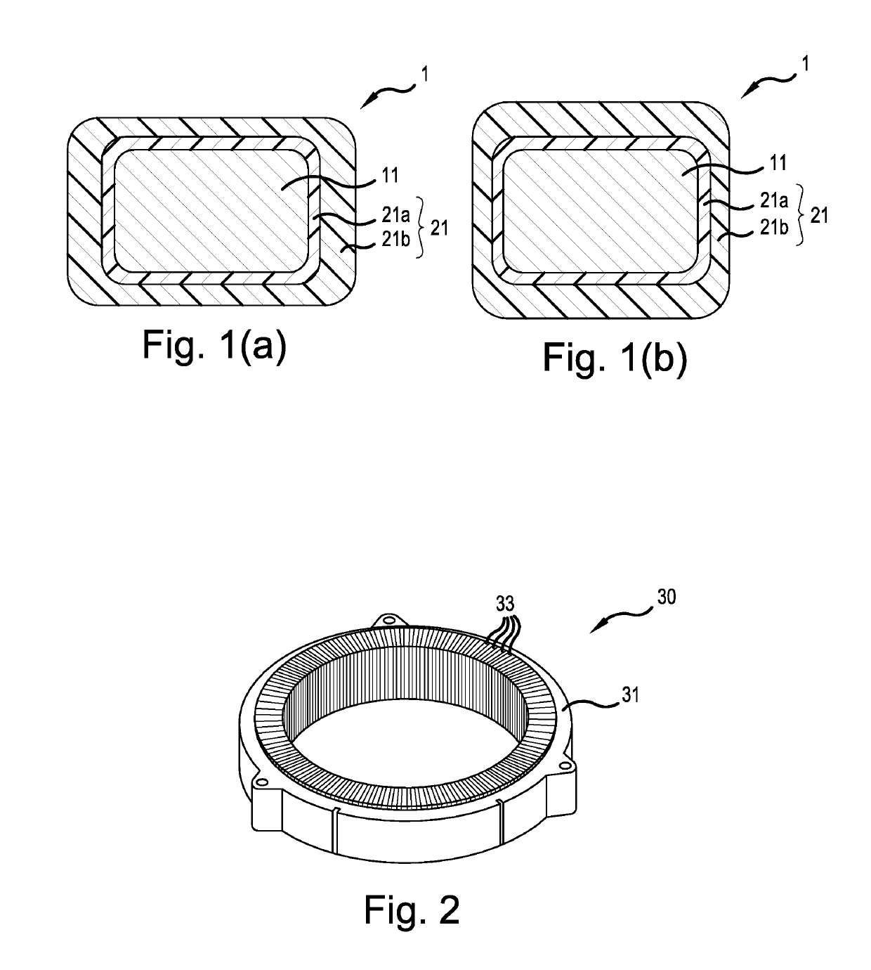
[0151]As a conductor 11, use was made of: a rectangular conductor having a rectangular cross-section (long side 3.2 mm×short side 1.5 mm, curvature radius of chamfered edges at four corners r=0.3 mm) (copper having an oxygen content of 15 ppm).

[0152]A polyamideimide (PAI) varnish (trade name: HPC-9000, manufactured by Hitachi Chemical, tensile modulus at 25° C.: 4,100 MPa) was coated on a surface of the conductor 11, with using a die having a similarity shape of a cross-sectional shape with the conductor, followed by passing through a 5 m-long natural convection-type baking furnace controlled the furnace inside temperature to 300 to 500° C. at the speed of 5 to 10 seconds passing time. This baking step was repeated several times, to thereby form the thermosetting resin layers with thickness 30 μm, thereby to give an enamel wire composed of the thermosetting res...

example 2

[0155]In Example 2, the insulated wire was produced, of the cross-sectional around rectangular shape, as shown in FIG. 4(a).

[0156]The insulated wire was produced in the same manner as in Example 1, except that the thickness of the thermosetting resin layers and the shape and the thickness of the thermoplastic resin layer would be changed to those shown in Table 1.

example 3

[0157]In Example 3, the insulated wire was produced, of the cross-sectional around rectangular shape, as shown in FIG. 4(a).

[0158]The insulated wire was produced in the same manner as in Example 1, except that the resin of the thermosetting resin layers was changed to polyimide (PI) varnish (trade name: U-VARNISH-A, manufactured by Ube Industries, Ltd., tensile modulus at 25° C.: 3,730 MPa), and that the thickness of the thermosetting resin layers and the shape and the thickness of the thermoplastic resin layer would be changed to those shown in Table 1.


PUM

PropertyMeasurementUnit
thicknessaaaaaaaaaa
thicknessaaaaaaaaaa
tensile elastic modulusaaaaaaaaaa

Abstract

An insulated wire, having at least one thermosetting resin layer and at least one thermoplastic resin layer in this order, as covering layers, on a conductor having a quadrilateral cross-section, wherein, in a coating thickness of the covering layers, in each side to be formed on 4 sides of the quadrilateral cross-section of said insulated wire, a difference between the maximum value and the minimum value is each 20 μm or less, and a value of the maximum value divided by the minimum value of the whole sides is 1.3 or more; a motor coil; and an electrical or electronic equipment.

Description

CROSS-REFERENCE TO RELATED APPLICATIONS[0001]This application is a Continuation of PCT International Application No. PCT / JP2017 / 005766 filed on Feb. 16, 2017, which claims priority under 35 U.S.C. § 119 (a) to Japanese Patent Application No. 2016-029455 filed in Japan on Feb. 19, 2016. Each of the above applications is hereby expressly incorporated by reference, in its entirety, into the present application.TECHNICAL FIELD[0002]The present invention relates to an insulated wire, a motor coil, and an electrical or electronic equipment.BACKGROUND ART[0003]In recent years, in electronic or electrical equipment (hereinafter, which may be simply referred to as electronic / electrical equipment), various performances, for example, heat resistance, mechanical properties, chemical properties, and electrical properties are become to be further highly enhanced more than ever before in those equipment, thus reliability has become required to be enhanced more than ever before in those equipment.[...

Claims


Application Information

Patent Timeline
Patent Type & Authority Patents(United States)
IPC IPC(8): H01B7/00H02K15/04H01B13/06H01B3/42H01B3/30H01F5/00H01B7/02H01F5/06H02K3/30H02K3/04H01B13/14
CPCH02K3/04H01B3/427H01B7/0009H01B3/306H01B7/00H01B7/02H01B13/065H02K15/04H01B3/305H02K3/30H01F5/06H01F5/00H01B7/0216Y02T10/641H01B13/148H01B3/307H01B3/301H01F7/02Y02T10/64
Inventor OYA, MAKOTOMUTO, DAISUKEFUJIWARA, DAI
Owner ESSEX FURUKAWA MAGNET WIRE LLC
Why Eureka
Try Eureka