
Pastes for thermal, electrical and mechanical bonding

a technology of thermal, electrical and mechanical bonding, applied in the direction of metal/alloy conductors, manufacturing tools, solventing apparatus, etc., can solve the problems of insufficient mechanical properties, inability to provide continuous thermal paths across the tim, and insufficient mechanical properties, so as to achieve high electronic and mechanical performance. , the effect of high bulk thermal conductivity

Active Publication Date: 2019-06-04
THE RES FOUND OF STATE UNIV OF NEW YORK
View PDF85 Cites 6 Cited by
  • Summary
  • Abstract
  • Description
  • Claims
  • Application Information

AI Technical Summary

Benefits of technology

The present technology uses composite nanomaterials in TIMs to manage thermal performance. The use ofAg nanoflakes and nanoparticles offers high bulk thermal conductivity, whereas copper nanoparticles offer flexibility in interfacial engineering. The technology also addresses the size distribution of particles, reproducibility, and the use of tightly controlled materials. It can improve performance in power electronics, high density microelectronics, electric vehicles, and household appliances. The patent also mentions the use of silver nanoparticles and organic materials to balance stability, dispersion, and fluidity, and describes the patterning of TIM layers for optimal performance. Overall, the technology enables efficient thermal management for various applications.

Problems solved by technology

In general, the larger particles provide high thermal conductivity, but alone may provide insufficient mechanical properties, such as ability to tolerate thermal cycling, hotspots, flexion, and the like.
Likewise, the larger particles alone may not provide continuous thermal paths across the TIM.
If the loading of large particles is too high, tolerance to mechanical stresses is impaired, and the layer thickness will tend to be thicker.

Method used


Image

  • Pastes for thermal, electrical and mechanical bonding
  • Pastes for thermal, electrical and mechanical bonding
  • Pastes for thermal, electrical and mechanical bonding

Examples


Embodiment Construction

[0085]FIG. 4 shows the steady state thermal gradient measurements on a microstructured nanopaste TIM showing interfacial thermal resistance of 2.4±0.2×10⁻⁶ (m2K / W) and bulk thermal conductivity of 20±1 (W / mK), for silver nanoparticles having a flake size of about 100 nm-1 μm, and a thickness of 10's of nanometers.

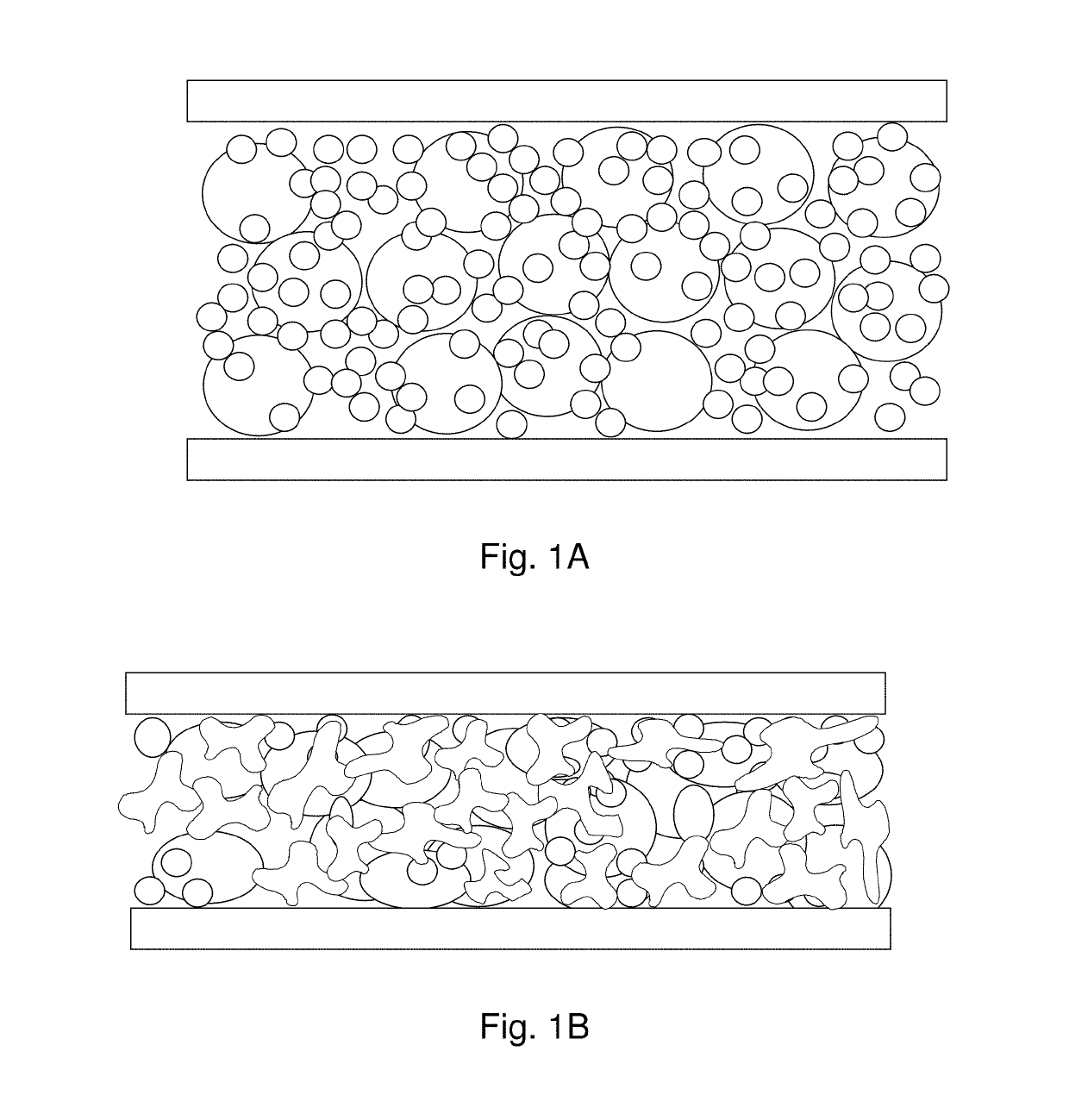
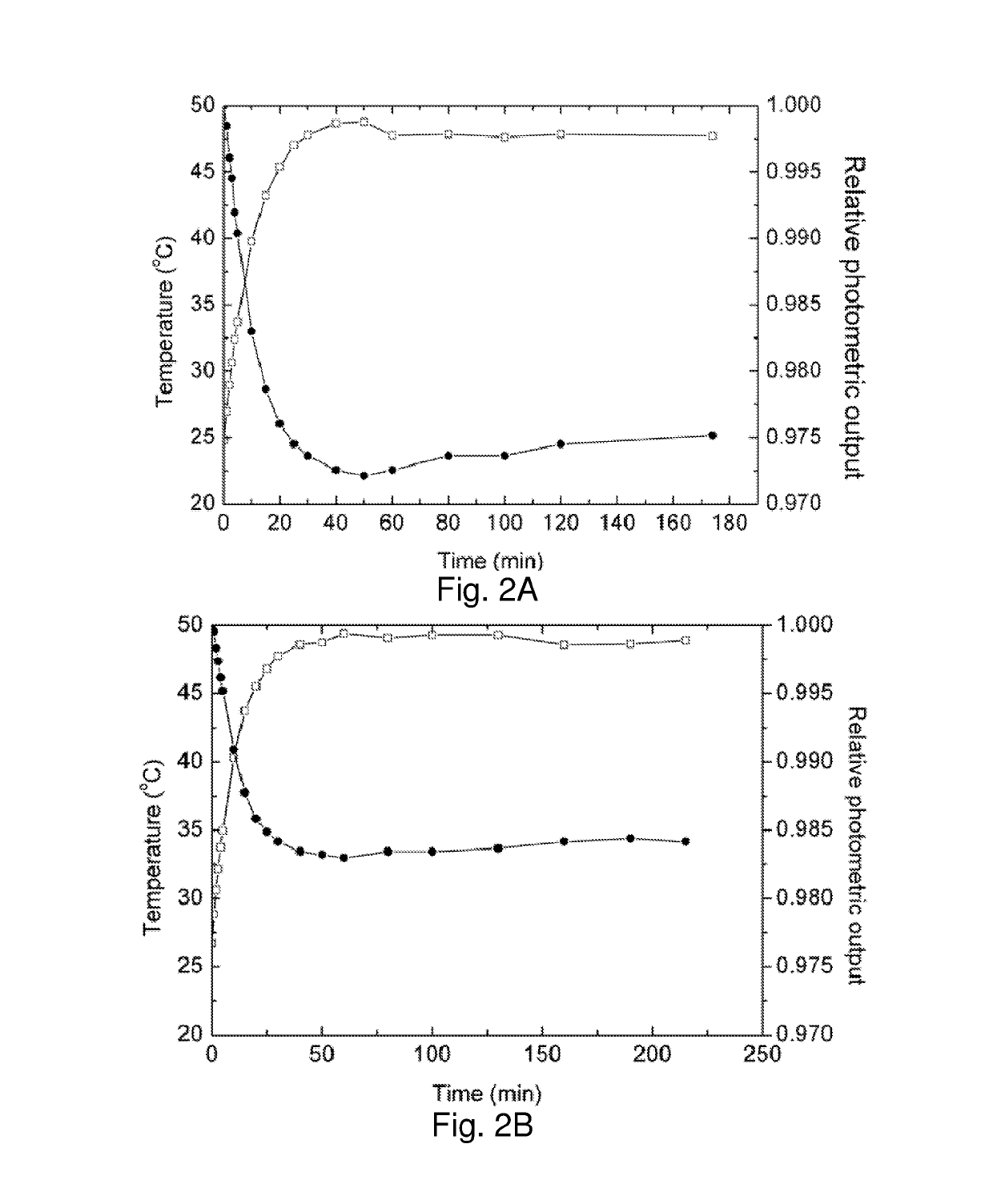
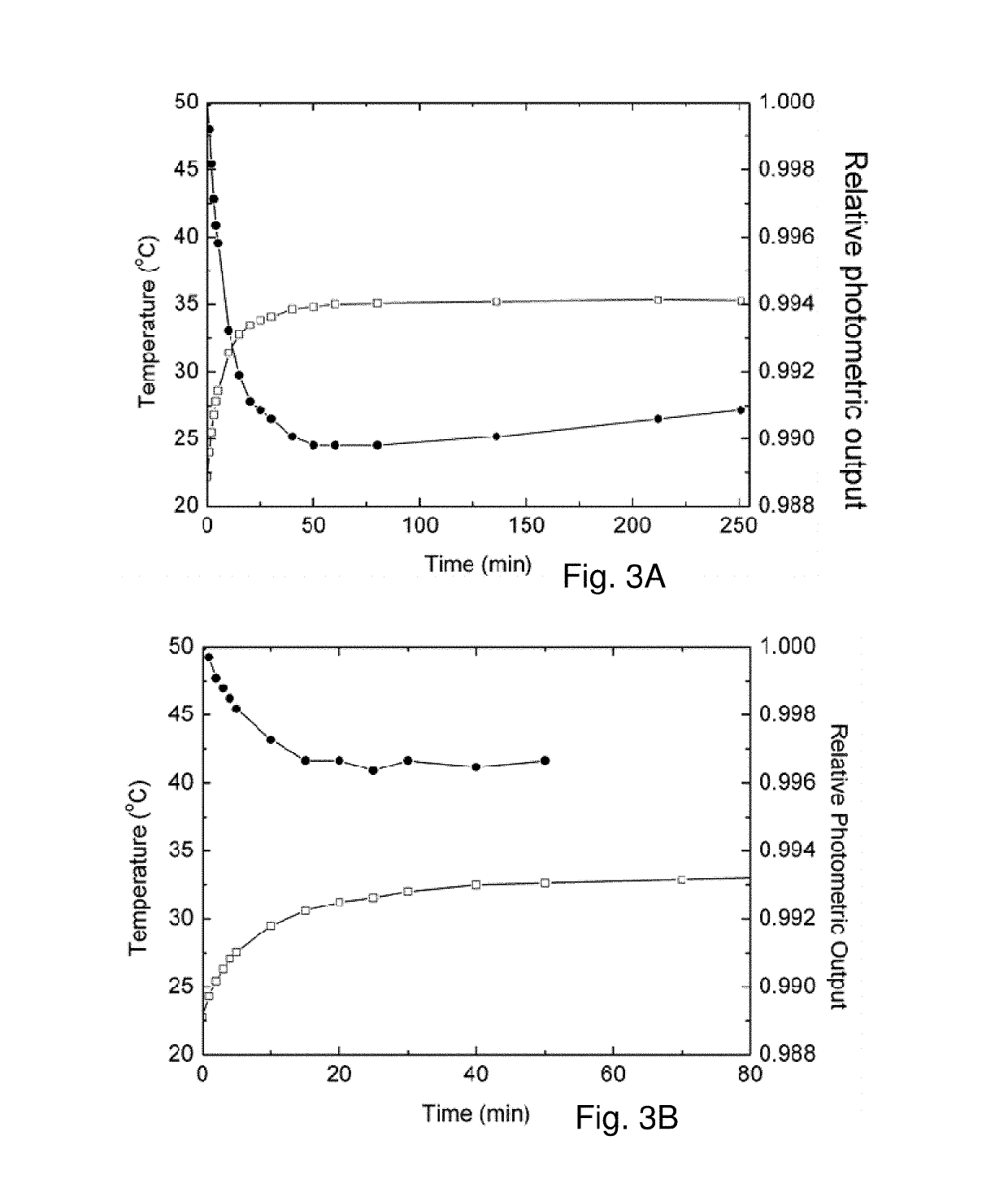
[0086]Tests prove the concept of Ag flake-particle combination nanopaste design and applications. For example, an LED's junction temperature has an impact on its luminescent efficiency. The test setup is shown in FIG. 1, which shows an LED array package on a heat sink, a photo detector to measure the luminescence, and a thermocouple to monitor junction temperatures. The power supply controls both the voltage and current to the 9 LED arrays, and maintains a constant power output at 7.4 W. Photo detector is fixed at a certain distance right above the LED lamp. Relative luminescence is calculated by normalizing the measured intensity to that at the initial time.

[0087]To mainta...


PUM

PropertyMeasurementUnit
Temperatureaaaaaaaaaa
Timeaaaaaaaaaa

Abstract

A class of paste materials for thermal, and mechanical bonding, and in some cases electrical interconnection, of two solid surfaces includes particles and an organic vehicle which is partially or completely removed during processing. The paste includes hybrids of inorganic materials for meeting the thermal, electrical and mechanical bonding functionality requirements and organic materials for meeting the process, application and protection requirements. The inorganic materials include high thermal and optionally electrical conductivity materials in forms from nanoparticles to micro-powders. The organic materials may include small molecules, surfactant, oligomers, and polymers.

Description

CROSS REFERENCE TO RELATED APPLICATION[0001]The present application is a Nonprovisional and claims benefit of priority from U.S. Provisional Patent Application No. 61 / 786,893, filed Mar. 15, 2013, the entirety of which is expressly incorporated herein by reference.FIELD OF THE INVENTION[0002]The present invention relates to thermal interface paste materials.BACKGROUND OF THE INVENTION[0003]Development of less-expensive and high performance power electronic devices is essential to support commercialization of new technologies from integrating energy harvesting and storage devices to electric vehicles to solid state lighting to high power microelectronics. One of major technical barriers is the ability of materials and components for efficient thermal management. Thermal interface materials (TIMs) play an important role in enabling a wide range of power electronics because TIMs account for over 50% of the heat dissipation in most high power devices. Low thermal resistance TIMs that ca...

Claims


Application Information

Patent Timeline
IPC IPC(8): B23K1/16B23K35/36B23K1/00C09K5/14H01B1/02
CPCC09K5/14B23K1/0016B23K35/36B23K2001/12H01B1/02
Inventor WANG, HAOSAMMAKIA, BAHGAT
Owner THE RES FOUND OF STATE UNIV OF NEW YORK
Learn More