Eureka AIR delivers breakthrough ideas for toughest innovation challenges, trusted by R&D personnel around the world.

Biocoated piezoelectric biosensor platform for point-of-care diagnostic use

a biosensor and biosensor technology, applied in the direction of instruments, analysing fluids using sonic/ultrasonic/infrasonic waves, ultrasonic/sonic/infrasonic waves, etc., can solve the problems of low sensitivity, high variability, and current state of art poc devices, etc., to achieve rapid poc diagnosis, simple manufacturing process, cost-effective

Active Publication Date: 2018-12-25
AVIANA MOLECULAR TECH
View PDF37 Cites 1 Cited by
  • Summary
  • Abstract
  • Description
  • Claims
  • Application Information

AI Technical Summary

Benefits of technology

The present invention is about using piezoelectric biosensors to diagnose diseases quickly and accurately. These biosensors are easy to make, inexpensive, and can be used as disposable tools in clinical diagnosis. They can detect specific markers of disease and are especially useful for diagnosing and monitoring infections. The invention also includes a method for increasing the energy of the surface of the piezoelectric material to improve the function of the biosensors.

Problems solved by technology

Current state of art POC devices, like lateral flow devices, do not meet this need, because of low sensitivity and / or high variability of results, among other flaws.
On the other hand, highly sensitive diagnostic tools such as nucleotide detection require sophisticated separation and processing, making these diagnostic devices difficult in field settings.
The laboratory based systems are accurate (both sensitive and specific), but they are not easily transportable or rapid and they require specially trained personnel to operate them.
However, the use of these devices as biosensors, made from piezoelectrically active materials such as crystals has had limited success either because the applied biological fluid suppresses the generated wave or because the applied films are difficult to manufacture consistently on a large scale, limiting them to resource-rich, sophisticated settings such as research laboratories.
Attempts at functionalizing these acoustic wave sensors as biosensors have resulted in tedious or inconsistent and difficult-to-scale-up processes.
These methods are often time consuming and the processes for coating complex.
However, this process is difficult to control for several reasons.
First, some of the silanes, such as trimethoxysilanes are very reactive; others, like triethoxysilanes, are less reactive but hydrolytically less stable.
Another reason is that because of the reactivity of silanes, their possession of several linkable groups and their tendency to react and link up with additional silane molecules, it is difficult to achieve a single layer of silane deposit which changes the transmission properties of the coated substrate in a manner difficult to control and maintain uniform.
The presence of even trace amounts of water additionally complicates process control because the silanes become even more prone to crosslinking by forming reactive silanols or silanediols.
The commonly used APTES is particularly prone to multilayer formation.
But these procedures involve wet chemistries and covalent bonds which complicate and delay the coating process and raise the possibility of side reactions, which would interfere with accuracy of the resulting device.
These stepwise processes may take hours or even several days and may yield SAM biosensors that are functionally variable, expensive and thus unacceptable for POC biosensor applications.
Such processes in the art are clearly not suitable for consistent and cost-effective manufacturing of uniform biosensors at low cost and in a scalable high-throughput mode of potentially millions of single use biosensors where process variations or failure would be highly undesirable.

Method used


Image

  • Biocoated piezoelectric biosensor platform for point-of-care diagnostic use
  • Biocoated piezoelectric biosensor platform for point-of-care diagnostic use
  • Biocoated piezoelectric biosensor platform for point-of-care diagnostic use

Examples


example 1

Manual Processes for Coating of Biosensor Chips Bearing Neutravidin and Biotinylated Antibody

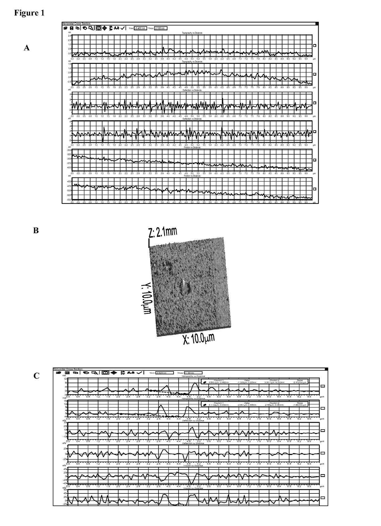
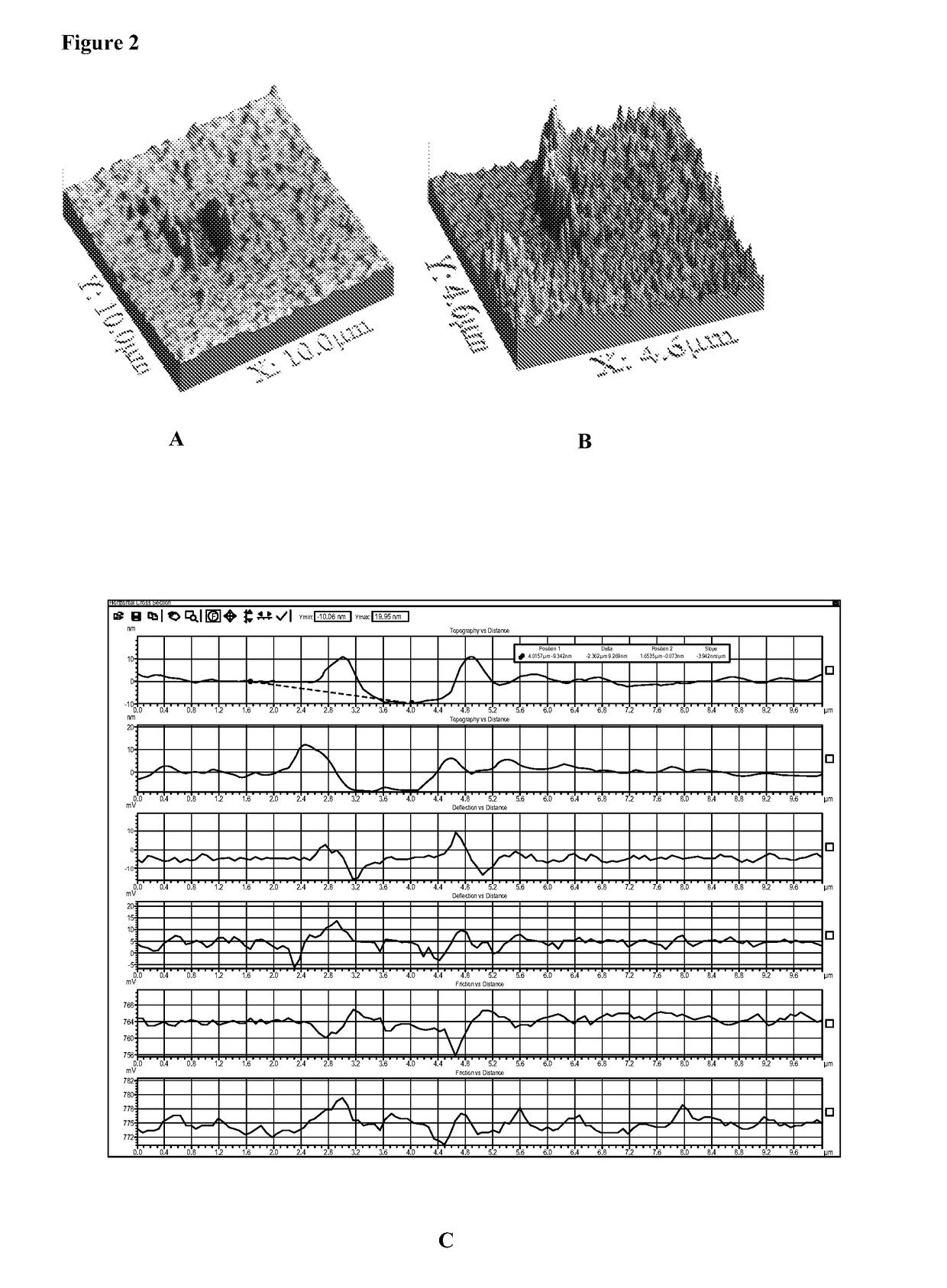
[0105]All of these methods have been actually performed.[0106]a. Coating without fixation: Clean and activate LiNbO3 surfaces for about 1-10 sec at atmospheric pressure with a plasma generating device (e.g. Plasma Treat USA, Elgin, Ill.) before application of avidin which is accomplished by inkjetting avidin in a solution containing 50% glycerol in PBS at an avidin concentration of 0.5 mg / ml, followed with brief drying using warm air from a heat gun at about 50° C. or drying at room temperature for about 30 min to bond the avidin to the surface, the biosensor is now ready for use or packaging.

[0107]Optionally, deposition of neutravidin is followed by a fixing step.[0108]b. Coating with thermal fixation: Neutravidin is applied by ink jetting as described in Example 1a. The neutravidin may be fixed to the piezo substrate by heating to about 30-50° C. with an infrared heat lamp for up to 30 min...

example 2

Automated Coating Processes

[0112]a. Automated Direct Coating Mode for Neutravidin Biosensors:

[0113]Online manufacturing of some embodiments involves deposition of neutravidin coating on piezo crystals affixed to the lower portion of the biosensor housing that is then mounted on a conveyor belt. After plasma treatment, the sensor is moved to the neutravidin inkjetting station and coated with 5-10 μl of fluid containing_0.01 to 5.0 mg / ml_neutravidin; or 0.01-2.0 mg / ml; or 0.01-1.0 mg / ml by weight per 0.5 cm square area. The fluid is evaporated and the neutravidin fixed on the biosensor by brief exposure to heat from a heat gun (about 50° C.). The upper cover of the housing is then affixed to form the leak proof fluid chamber of the biosensor cartridge.[0114]b. Automated Coating Mode for Coated Neutravidin Having Biotinylated Antibody:

[0115]A similar inkjet process as described above in 2a is used to coat the biotinylated antibody diluted to a suitable dilution in a non-drying stabiliz...

example 3

Chlamydia trachomatis Detected on the Biosensor

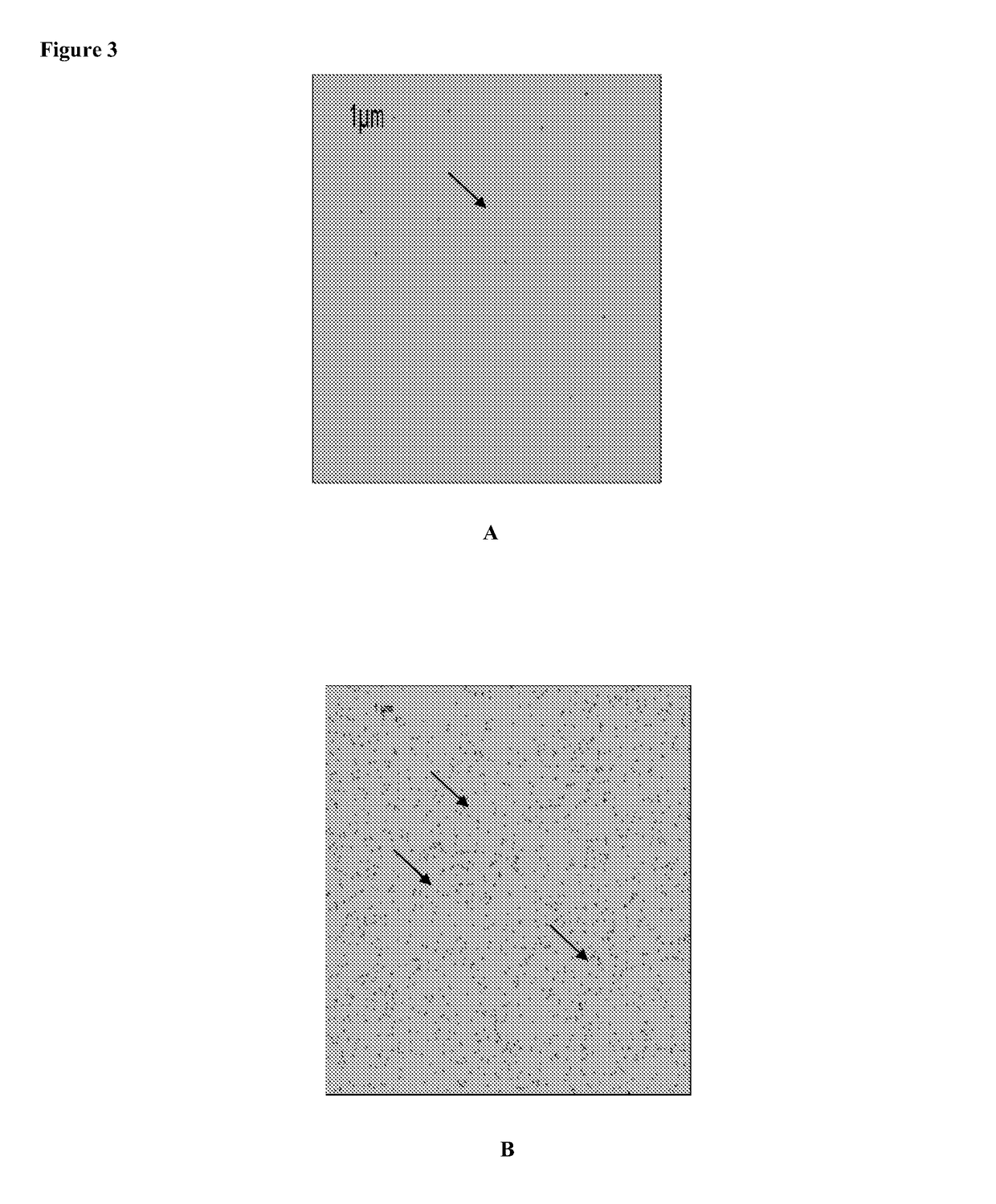
[0120]Experiments were conducted with C. trachomatis, an obligate intracellular bacterium which causes a sexually transmitted disease in both women and men. The procedures used to coat avidin and antibody are described in Example 1. The antibody used is a monoclonal antibody against the major outer membrane (MOMP) of C. trachomatis (Abcam) biotinylated and used at 0.25 μg / ml. C. trachomatis was obtained from Microbia and was suspended in PBS / Buffer at a concentration of 105 per ml in a similar experiment, monoclonal antibody directed against C. trachomatis elementary body lipopolysaccharide (Medix). A aliquot of elementary bodies (EB) of 105 EB+0.25 μg / ml of biotinylated anti-EB LPS was incubated for 30 minutes at RT and then added to the chip. FIGS. 6 and 7 depict the results of experiments conducted with these specific infectious antigens. FIG. 6 is a series of black and white tracings of a fluorescent microscopy slide taken of an AMT...


PUM

PropertyMeasurementUnit
depthaaaaaaaaaa
depthaaaaaaaaaa
depthaaaaaaaaaa

Abstract

Biosensor components (chips) are described based on direct biocoating processes that result in the tenacious and stable, noncovalent (believed to be chemisorptive) binding of anchor substances such as avidin(s) other proteins having specific binding partners or oligo- or poly-nucleotides onto any piezo-electrically active crystal surface. The resulting platform technology can be developed for a variety of biosensors with specific applications in biological assays. The table mono layers of the anchor substances forms reactive layers, ready to bind a capture reagent such as a biot-inylated antibody for capture and detection of analytes in biologic fluid samples. Although the processes described herein can be performed on any type of piezoelectric material in any number of configurations, some embodiments are directed to a biosensor with the foregoing biocoating onto a particular acoustic plate mode biosensor and where the interdigitated transducers (IDTs) are present on the opposite side of the crystal's biocoated film.

Description

[0001]This application is being filed on 26 Feb. 2014, as a U.S. National Stage of PCT International Patent application No. PCT / US2012 / 052583, filed 27 Aug. 2012 in the name of Aviana Molecular Technologies, LLC, a U.S. national corporation, applicant for the designation of all countries except the US, Lisa Laury-Kleintop, a citizen of the U.S., Hsu-Cheng Ou, a citizen of Taiwan, and Herman Rutner, a citizen of the U.S., applicants for the designation of the US only, and claims priority to U.S. Provisional Patent Application Ser. No. 61 / 527,716, filed Aug. 26, 2011. and which applications are incorporated herein by reference. To the extent appropriate, a claim of priority is made to each of the above disclosed applications.FIELD OF THE INVENTION[0002]The present invention relates generally to devices and methods for analyzing test samples containing target analytes including proteins and nucleic acids. The invention uses integrated chips as sensitive biosensors having a biocoating w...

Claims


Application Information

Patent Timeline
Patent Type & Authority Patents(United States)
IPC IPC(8): G01N33/551H01L41/113H01L41/253B05D3/14G01D5/14G01N29/22G01N29/34G01N29/36G01N29/02G01N33/543G01N33/569H10N30/04H10N30/30H10N30/85
CPCG01N33/54306G01D5/14G01N29/02G01N29/022G01N29/22G01N29/34G01N29/36G01N33/54386G01N33/551G01N33/56927G01N33/56983H01L41/113H01L41/253B05D3/142G01N2291/0427G01N2291/0255G01N2291/0256H10N30/30H10N30/04
Inventor LAURY-KLEINTOP, LISARUTNER, HERMAN
Owner AVIANA MOLECULAR TECH
Why Eureka
Eureka Blog
Learn More