
Ultra high strength nanomaterials and methods of manufacture

Active Publication Date: 2018-08-28
FARBSTEIN NEIL
View PDF27 Cites 21 Cited by
  • Summary
  • Abstract
  • Description
  • Claims
  • Application Information

AI Technical Summary

Benefits of technology

This patent describes a method of making strong and high-strength materials using carbon nanoparticles. The carbon nanoparticles, such as graphene nanosheets, are mixed with carbide-forming nanoparticles and then assembled using a vacuum to create a nanopaper. This nanopaper is then heated in a hot press to fuse the nanoparticle structures into aligned structures with high values for strength, bending strength, and tension modulus. The process also results in materials with increased hardness and lubricity, as well as decreased contact resistance, increased heat conductivity, and increased electrical conductivity. These materials have valuable properties such as high fracture toughness, magnetic, photonic, and insulating properties.

Problems solved by technology

Although the SPS process was shown to link defluorinated MWNT carbon nanotubes with each other into high strength, high conductivity carbon materials, MWNT carbon nanotubes are expensive and it will be desirable to use less costly starting materials to manufacture similar materials.
SPS processing is expensive and limited to small articles of manufacture also.
Although the nanoscale coalescence of double walled carbon nanotubes was noted as a reproducible phenomenon, no method has been found to promote extensive fusion of nanotubes in a bulk material.
Their process is limited to carbon nanotube nanopaper and cannot mass produce bulk solid materials having the high Young's modulus they achieved with 9 cm2 pieces of nanopaper.
Their materials have the further disadvantage that they contain polymer matrixes that will burn and decompose under high temperature oxidative conditions.
They will be weakened by exposure to organic solvents used in chemical processing industries also.
Its tensile strength is exceeded by that of graphite fibers and carbon nanotubes are much more expensive than graphite fiber composites with comparable young's modulus.
Although slippage in polymer matrixes is reduced, it is still present to a lower degree, and the remaining amounts of slippage are large enough to cause reductions in the strength of the composite materials, and they fail to attain the strength of their constituent carbon nanotubes—1 TPa and greater.
The lower Young's modulus and tensile strength of the polymer matrix in comparison with the strength of the nanotubes reinforcing those composites also reduces the overall strength of that type of composite material.
The prior art fails to provide methods of manufacturing DWNT objects big enough to be seen with the naked eye with these characteristics.
Nor does it provide methods of manufacturing bulk materials such as nanopaper, fibers, or useful macroscopic articles with ultra high young's modulus.
Their methods resulted in nanostructures that were all unlinked.
They can be in shapes such as plates, fibers, spheres, films or any regular or irregular shapes” The above prior art patent also does not provide materials or methods for manufacturing inorganic carbide nanograined materials fashioned into nanopaper, laminated composites, solid articles, molded articles and high strength structural reinforcing materials.
The prior art patent is also limited to graphene and graphite powders and makes no claims about covalently bonding carbon nanotubes or other carbon nanoparticles useful for manufacturing ceramic nanomaterials.
And it has no provision for connecting the graphene nanosheets with fused nanostructures that weld them together into extremely high strength materials.

Method used


Image

  • Ultra high strength nanomaterials and methods of manufacture
  • Ultra high strength nanomaterials and methods of manufacture
  • Ultra high strength nanomaterials and methods of manufacture

Examples


Embodiment Construction

Brief Description of Drawings and Reference Numerals

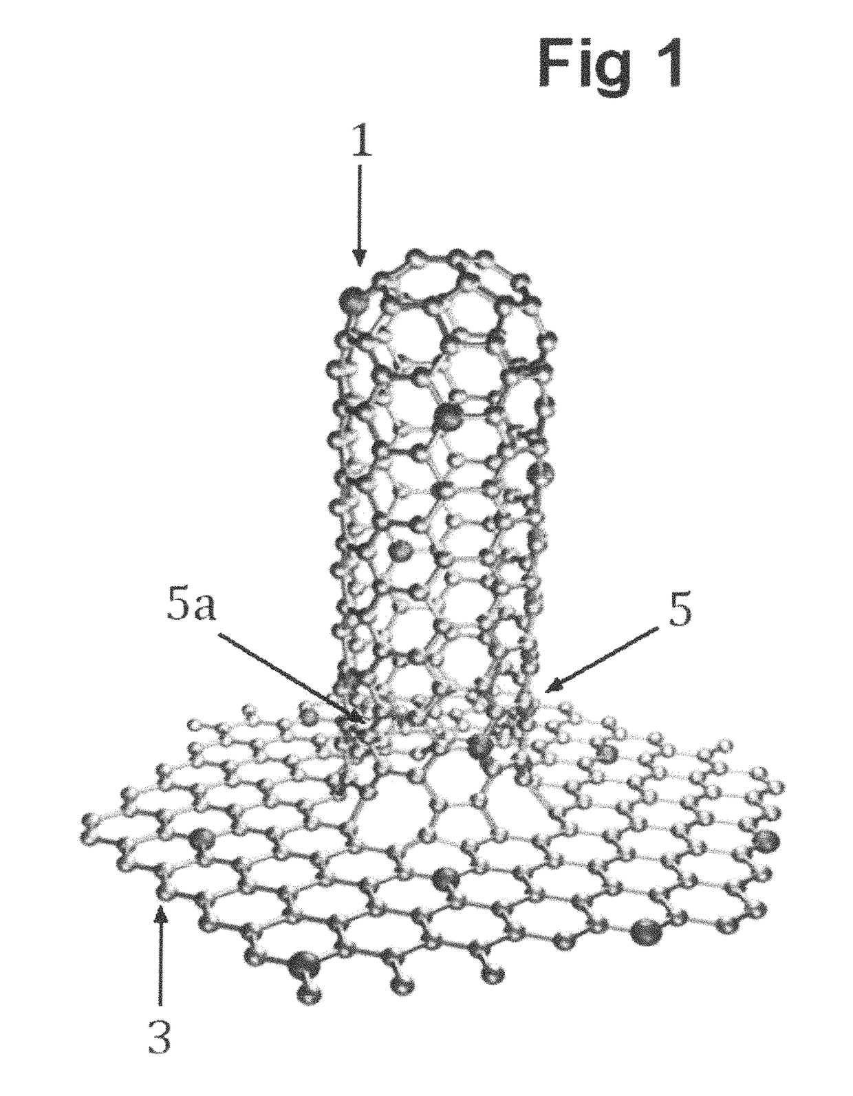
[0030]FIG. 1 Hybrid nanostructurecarbon nanotube fused to graphene nanosheet[0031]1 top of carbon nanotube[0032]3 graphene nanosheet[0033]5 joining region of fused carbon nanotube and graphene structures[0034]5a joining region of fused carbon nanotube and graphene structures

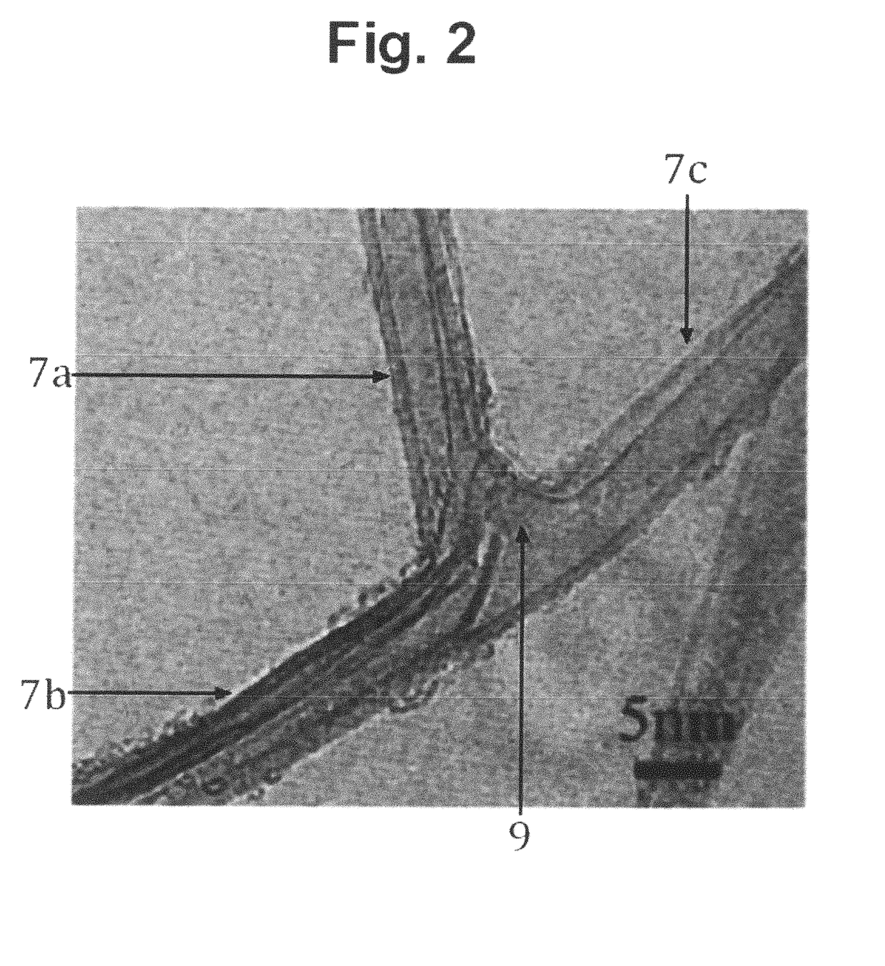
[0035]FIG. 2 Two double walled carbon nanotubes fused together into triple junction[0036]7a double walled carbon nanotube region[0037]7b double walled carbon nanotube region[0038]7c double walled carbon nanotube region[0039]9 triple junction weld

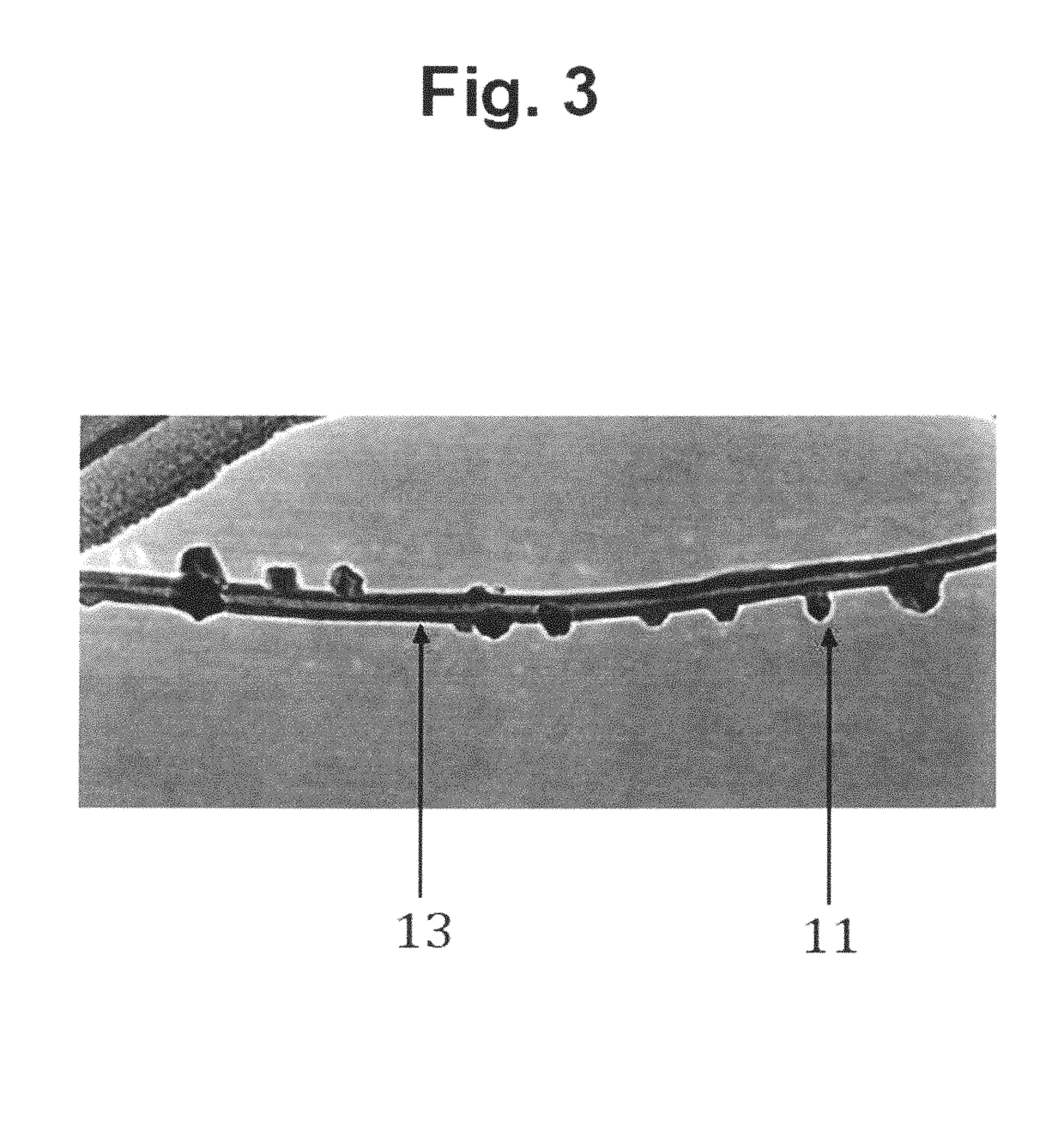
[0040]FIG. 3 TEM image of carbon nanotube with 14 boron carbide nanolumps fused to it[0041]11 boron carbide nanolump fused to multiwalled carbon nanotube[0042]13 multiwalled carbon nanotube

[0043]FIG. 4 Densified carbon nanotube—boron carbide nanolump material[0044]11a MWNT carbon nanotube[0045]13a boron carbide nanolump fused to MWNT[0046]13b boron carbide nanolump fused to MWNT[0047]15 boron carbide nanolump fused betw...


PUM

PropertyMeasurementUnit
Temperatureaaaaaaaaaa

Abstract

A general method of manufacturing high strength ultrafine grained nanostructured carbon and carbide materials that combines densification of nanoparticles with heat treatments or other means of supplying energy to cause fusion of structures that interlink and weld the nanoparticles together. Coatings films, nanopaper, nanopaper laminates, fibers, and extended objects can be manufactured by applying the disclosed methods. The nanomaterials are useful for additive manufacturing of rapid prototyped objects. A variety of nanoparticle starting materials are divulged including but not limited to double walled carbon nanotubes, fluorinated graphene nanosheets, silicon nanowires, and boron nanoplatelets. Articles can be manufactured with spark plasma synthesis, capacitive discharge sintering, hot press apparatus and green bodies can be processed in furnaces. The nanomaterials and ultra high strength articles manufactured from them will have applications including laparoscopic instruments, structural composites, heat sinks, EMI shielding, ballistic protection and aerospace components.

Description

[0001]This patent claims the benefit of Provisional Patent Ser. No. 61 / 069,147 filing date Mar. 13, 2008 which is incorporated by reference[0002]This patent claims the benefit of Provisional Patent Ser. No. 61 / 878,328 filing date Sep. 16, 2013 which is incorporated by referencePRIOR ART[0003]State of the art structural materials composed of carbon nanoparticles have aggregate tensile strength, bending strength, toughness, compressive strength and other strength parameters that are much lower than the strength of their constituent nanoparticles. For example; carbon nanotubes and graphene nanosheets can have Young's moduli of 1 terrapascal (TPa) or greater while the typical top tensile strength of graphene nanopaper rarely exceeds 30 gigapascals (GPa). The strength of carbon nanotube nanopaper is even lower—in the single gigapascal range. Even low quality carbon fibers and glass fibers exceed graphene paper in strength.[0004]Spark plasma sintering (SPS) of fluorinated MWNT was observe...

Claims


Application Information

Patent Timeline
IPC IPC(8): H01B1/04C25D13/00C09D1/00C25D5/54B29C43/00B05D1/02B82Y40/00B82Y30/00B29L31/00
CPCC01B31/36B05D1/02B29C43/006B29C43/003C09D1/00C25D5/54C25D13/00B29L2031/00Y10S977/752Y10S977/75Y10S977/734B82Y30/00B82Y40/00C08K3/046C09D7/61C09D7/70C01B32/956B29K2105/162B29K2507/04B29K2995/0077B29C43/56B29C2043/561B29K2507/02C25D13/22C08K3/04C08K2201/001
Inventor FARBSTEIN, NEIL
Owner FARBSTEIN NEIL
Learn More