Multilayer capacitor
A technology of laminated capacitors and terminal electrodes, which is applied in the direction of laminated capacitors, fixed capacitor electrodes, and fixed capacitor dielectrics, can solve the problem of not increasing the equivalent series resistance of laminated capacitors, and achieve the goal of increasing the equivalent series resistance Effect
- Summary
- Abstract
- Description
- Claims
- Application Information
AI Technical Summary
Problems solved by technology
Method used
Image

Examples
no. 1 Embodiment approach
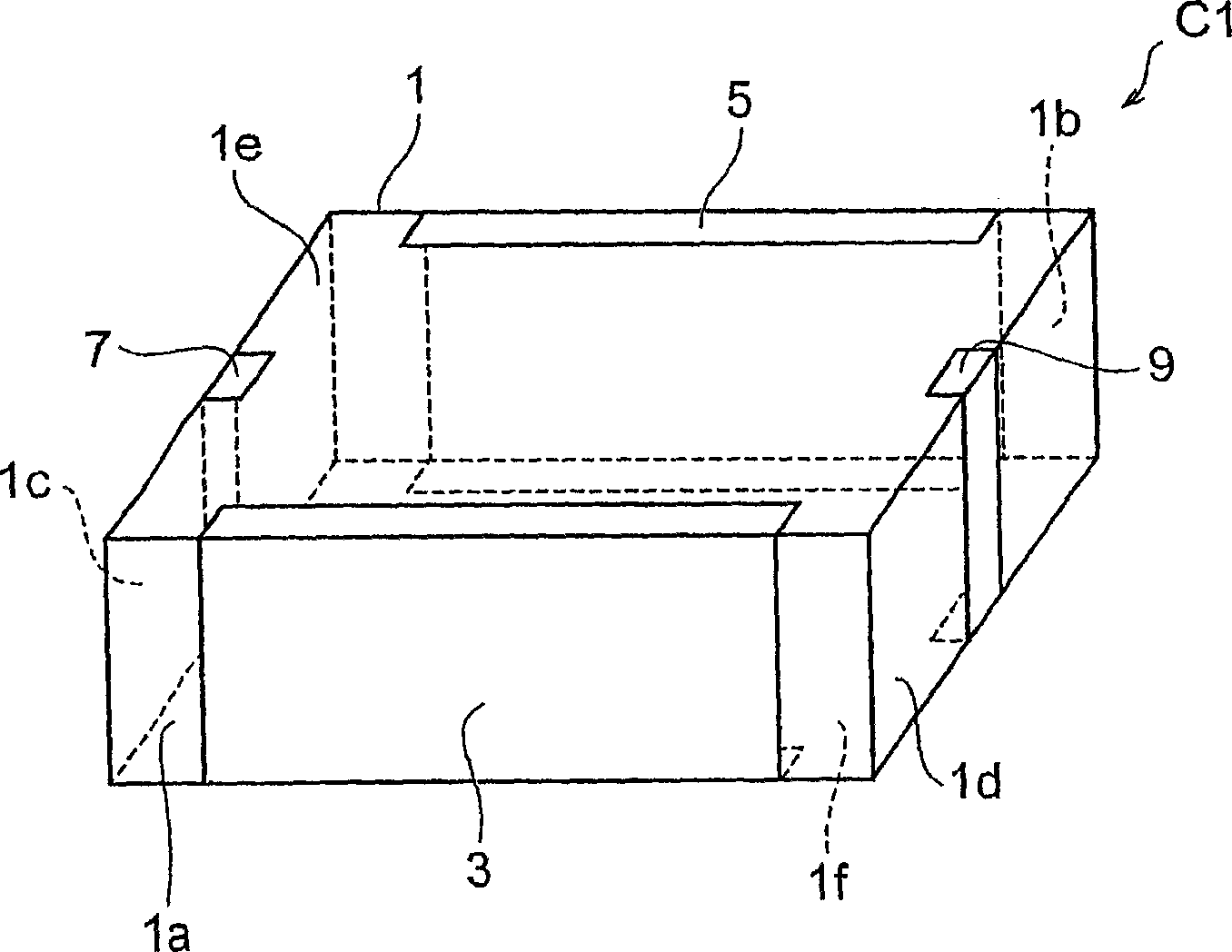
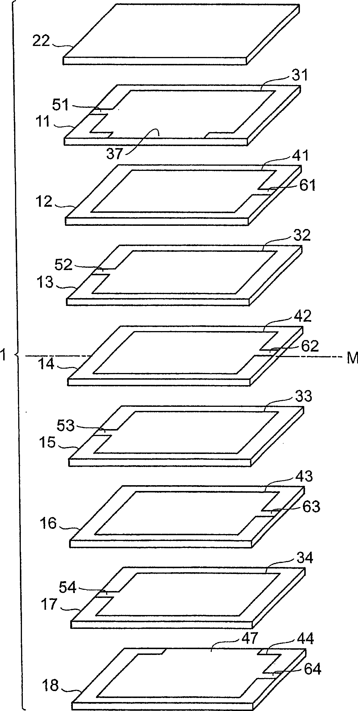
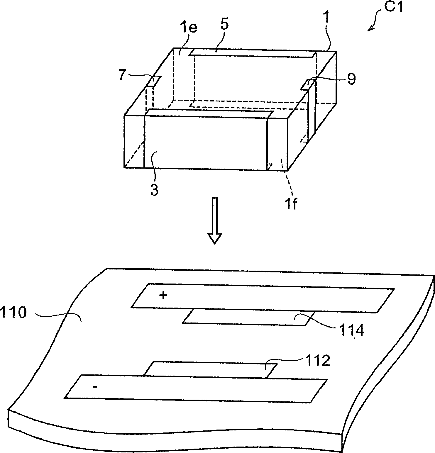
[0053] refer to figure 1 as well as figure 2 The configuration of the multilayer capacitor C1 according to the first embodiment will be described. figure 1 It is a perspective view of the multilayer capacitor according to the first embodiment. figure 2 It is an exploded perspective view of a laminate included in the multilayer capacitor according to the first embodiment.
[0054] Multilayer capacitor C1, as figure 1 As shown, a laminated body 1 , first and second terminal electrodes 3 and 5 formed on the laminated body 1 , and first and second connection conductors 7 and 9 are included.
[0055] The first terminal electrode 3 is formed on the side surface 1 a extending in the longitudinal direction among the side surfaces parallel to the lamination direction described later of the laminated body 1 . The second terminal electrode 5 is formed on the side surface 1b extending in the longitudinal direction and facing the side surface 1a on which the first terminal electrode ...
no. 2 Embodiment approach
[0075] refer to Figure 5 The structure of the multilayer capacitor according to the second embodiment will be described. The multilayer capacitor according to the second embodiment differs from the multilayer capacitor C1 according to the first embodiment in that the first internal electrode 33 connected to the first terminal electrode 3 via the lead-out conductor 37 and the first internal electrode 33 connected to the first terminal electrode 3 via the lead-out conductor 47 are different from the multilayer capacitor C1 according to the first embodiment. The position of the second internal electrode 42 connected to the second terminal electrode 5 in the stacking direction. Figure 5 It is an exploded perspective view of a laminate included in the multilayer capacitor according to the second embodiment.
[0076] The multilayer capacitor according to the second embodiment is omitted from illustration, but it includes a laminated body 1 and a first terminal electrode formed on...
no. 3 Embodiment approach
[0086] refer to Figure 6 The structure of the multilayer capacitor according to the third embodiment will be described. The multilayer capacitor according to the third embodiment differs from the multilayer capacitor C1 according to the first embodiment in that the first and second inner electrodes 31 and 34 are connected to the terminal electrodes 3 and 5 via lead-out conductors 37 and 47 . , 41, 44 numbers. Figure 6 It is an exploded perspective view of a laminate included in the multilayer capacitor according to the third embodiment.
[0087] The multilayer capacitor according to the third embodiment is omitted from illustration, but it includes a laminated body 1 and a first terminal electrode 3 formed on the multilayered body 1 similarly to the multilayered capacitor C1 according to the first embodiment. , the second terminal electrode 5 formed on the same laminated body 1 , and the first and second connection conductors 7 and 9 .
[0088] In the multilayer capacitor...
PUM
 Abstract
Description
Claims
Application Information
 - Generate Ideas
- Intellectual Property
- Life Sciences
- Materials
- Tech Scout
- Unparalleled Data Quality
- Higher Quality Content
- 60% Fewer Hallucinations
Browse by: Latest US Patents, China's latest patents, Technical Efficacy Thesaurus, Application Domain, Technology Topic, Popular Technical Reports.
© 2025 PatSnap. All rights reserved.Legal|Privacy policy|Modern Slavery Act Transparency Statement|Sitemap|About US| Contact US: help@patsnap.com