
Heat pipe

A heat pipe and copper pipe technology, applied in the field of heat pipes, can solve the problems of high processing defect rate, large product scrap, and high finished product defect rate, and achieve the effects of high post-processing qualification rate, simple production process and low production cost.

Inactive Publication Date: 2006-08-09
李国辉
View PDF1 Cites 6 Cited by
  • Summary
  • Abstract
  • Description
  • Claims
  • Application Information

AI Technical Summary

Problems solved by technology

The current heat conduction materials used in heat pipes are copper mesh, copper fiber, copper powder sintered or copper granule. Fast, high output, but high defect rate in subsequent processing, large damage to finished products, and low thermal conductivity durability; although copper fiber-like materials are low in production cost and high in output, they have large post-processing deformation, low thermal conductivity in flattened form, and product scrapping Large; copper powder sintered material has fast heat conduction, but its production cost is high, output is low, loss is large, and the defective rate of post-processing products is high; copper granular material has low cost, fast heat conduction, and high output, but subsequent processing is easy to deform and process Low thermal conductivity and high defective rate after finished product processing
As the operating speed of various machines and equipment is getting higher and higher, the heat generated is increasing greatly. The above-mentioned heat-conducting materials can no longer meet the demand of heat dissipation. Therefore, it is absolutely necessary to provide a better heat dissipation performance. heat pipe

Method used


Image

  • Heat pipe
  • Heat pipe

Examples


Embodiment Construction

[0017] Below in conjunction with accompanying drawing and specific embodiment the present invention is described in further detail:

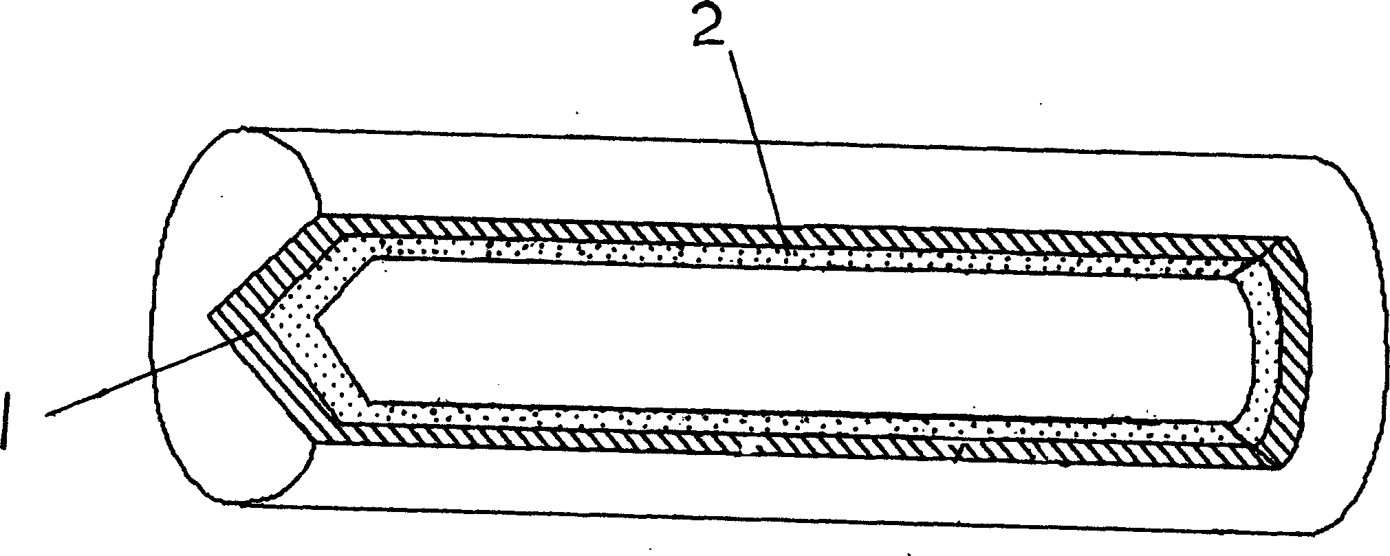
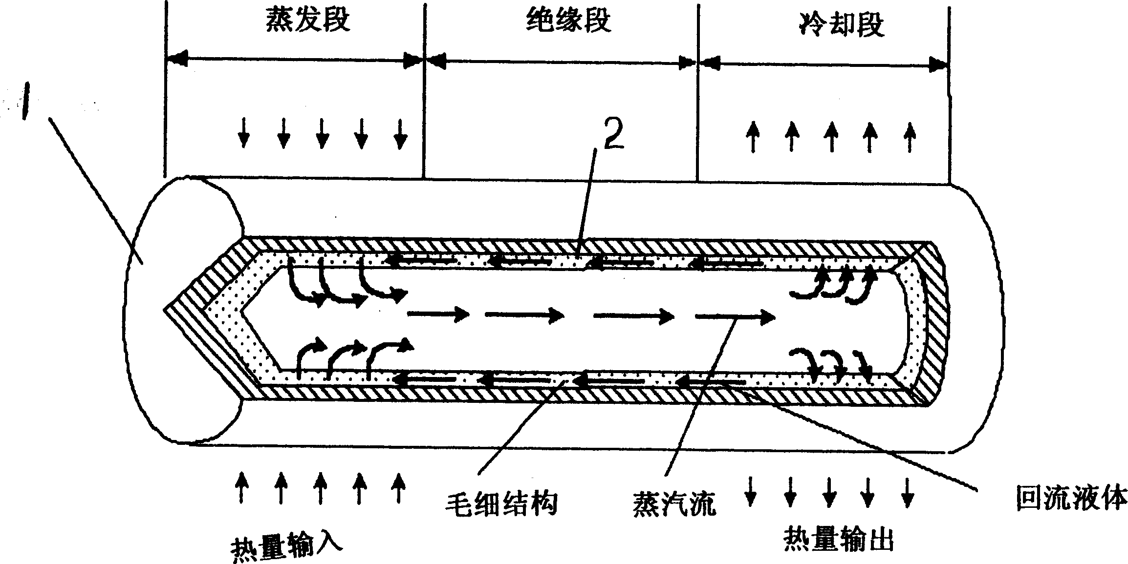
[0018] A heat pipe includes a sealed external container 1, and a heat-conducting material 2 made of foam metal and a working fluid injected into the external container 1 are arranged in the external container 1. After the working fluid is injected into the external container, it quickly seeps into the pores of the foam metal. The basic principle of heat transfer in the present invention is: the heat conduction of the heat pipe is the mechanism of using the latent heat of the working fluid in the tube to transport heat when the temperature changes. Because it can operate under a small temperature difference, it can have amazing heat transfer. Therefore, it has the reputation of thermal superconductor. In this way, when one end of the heat pipe is heated, the heated energy will vaporize the working fluid stored in the metal foam pipe wall, and at...


PUM


Abstract

Present invention discloses a thermal pipe. It contains sealed external use container with heat conductive material and filled operating fluid. It features said heat conductive material being foamed metal. Due to foam copper etc foamed metal having uniform pore with fine connectivity and simple process, the heat conductive material made from said foamed metal can absorb uniformly operating fluid like sponge and equalization dispersed over thermal pipe circumference, letting any point of thermal pipe heat radiation, said invention having fast heat transfer, high heat conduction quantity, less loss, yield quantity, low production costs, simple manufacturing process etc advantages.

Description

【Technical field】 [0001] The invention relates to a heat pipe, in particular to a heat pipe in which metal foam is arranged. 【Background technique】 [0002] At this stage, metal foams such as copper foam have been widely used in the fields of filtration, separation, sound absorption, flame retardancy and catalysis. There are many methods for their production. For example, patent 00127500.3 introduces a metal foam manufacturing method with uniform pores and simple process. The percolation method has good formability and stable quality. [0003] As we all know, the heat conduction of the heat pipe is the mechanism of using the latent heat of the working fluid in the tube to transport heat when the temperature changes. Because it can operate under a small temperature difference, it can have an amazing heat transfer, so it has the reputation of a thermal superconductor. . The current heat conduction materials used in heat pipes are copper mesh, copper fiber, copper powder sint...

Claims


Application Information

Patent Timeline
IPC IPC(8): F28D15/02
Inventor 李国辉
Owner 李国辉
Learn More