Shaping circular light three differential confocal microscope

A differential confocal and ring light technology, applied in the direction of microscopes, optics, optical components, etc., can solve problems such as side lobe increase, ambient temperature drift, and nonlinear error increase of axial response curve, so as to improve lateral resolution ability, extended axial range, and improved tomographic accuracy

Inactive Publication Date: 2005-03-02
HARBIN INST OF TECH
View PDF1 Cites 16 Cited by
  • Summary
  • Abstract
  • Description
  • Claims
  • Application Information

AI Technical Summary

Problems solved by technology

Generally speaking, the above-mentioned new confocal microscope and super-resolution technology have improved the resolution characteristics of the confocal microscope and solved the needs of many confocal microscope super-resolution microscopic imaging measurements, but they still have the following problems: First, the existing Various forms of confocal microscopes use the detected light intensity signal to directly perform imaging processing, which is easily affected by factors such as light intensity fluctuations, background light interference, and environmental temperature drift. The signal-to-noise ratio of the confocal microscope imaging system is low; The axial tomographic accuracy of the confocal microscope is limited by the nonlinearity of the axial intensity response curve, and the existing super-resolution technology tends to cause the increase of the side lobe and the increase of the nonlinear error of the axial response curve during the super-resolution imaging process
However, the three-differential confocal microscopy imaging method is mainly used to improve the axial resolution of the confocal microscope, and does not improve the lateral resolution. When the existing super-resolution pupil filter is used for three-dimensional super-resolution measurement of the confocal microscope, both It is necessary to perform horizontal super-resolution and also take into account axial super-resolution. The effect of three-dimensional super-resolution is usually not particularly significant.

Method used


Image

  • Shaping circular light three differential confocal microscope
  • Shaping circular light three differential confocal microscope
  • Shaping circular light three differential confocal microscope

Examples


Embodiment Construction

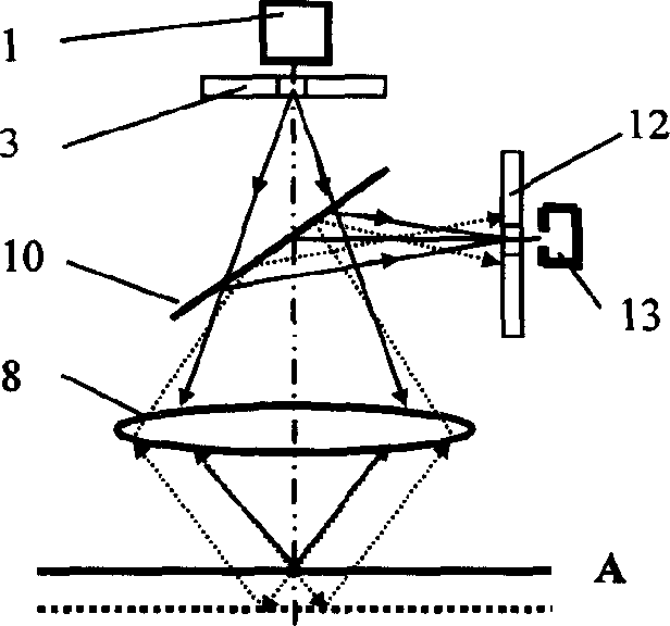
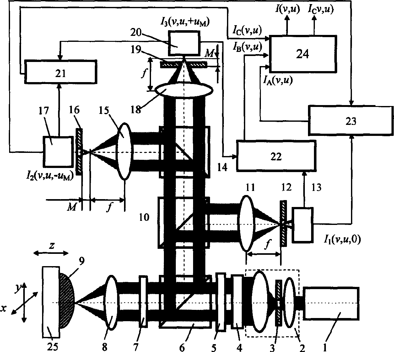
[0032]The technical principle of the present invention is: using the three-differential confocal microscopic imaging technology, the receiving optical path of the confocal microscope is arranged as a three-way detection light path of far focus, focal plane and near focus, and the three-way intensities with different phases detected by the three-way detection system Response signals are differentially subtracted in pairs to achieve the purpose of improving axial resolution and anti-interference ability; in addition, by increasing the proportion of high-frequency light in the laser beam irradiation system, the main Airy disk of the three-differential confocal microscope system The petal becomes smaller, so as to improve the spatial resolution of the confocal microscope system, and integrate the lateral super-resolution characteristics of the shaped ring light with the axial high-resolution characteristics of the differential confocal microscopy technology, so as to achieve high pe...


PUM


Abstract

The invention belongs to optical microscope imaging and microcosmic measurement field, which relates to an integral ring light three-difference cofocal microscope with high signal-to-noise ratio and three-dimension super resolution imaging ability; it mainly includes laser, beam expanding device, polarization spectroscope, lambda / 4 wave plate, microscope lens, gathering lens; and pin apertures and detectors, it also includes a ring light integral device whose incidence light is ring type between the beam expanding device and the polarization spectroscope, adjusts the adjustable diaphragm. The invention improves the transverse resolution of the microscope.

Description

technical field [0001] The invention belongs to the technical field of optical microscopic imaging and microscopic measurement, and relates to a three-dimensional ring-light three-differential confocal microscope with high performance-to-noise ratio and three-dimensional super-resolution imaging capability, which can be used to measure three-dimensional surface topography, three-dimensional Microstructure, microsteps, microgrooves, integrated circuit line width, etc. Background technique [0002] The idea of ​​confocal microscopy was first proposed by American scholar M.Minsky in 1957, and was authorized by the US patent in 1961, the patent number is US3013467. The confocal microscope places the point light source, point object, and point detector in corresponding conjugate positions, forming a point illumination and point detection microscopic imaging system with unique tomographic capabilities in optical microscopic imaging. The basic principle of general confocal microsc...

Claims


Application Information

Patent Timeline
IPC IPC(8): G02B21/00G02B27/10G06F3/00
Inventor 赵维谦谭久彬邱丽荣
Owner HARBIN INST OF TECH
Why Eureka
Try Eureka