Manufacturing method of optical fiber optical fluid channel

A fabrication method and fluid channel technology, which are applied in the directions of cladding optical fibers, optical waveguides, and structures/shapes of active media, can solve the problems of unavailability, complex technology, and high viscosity of paraffin oil, and achieve simple, easy-to-implement, low-cost effects

Pending Publication Date: 2022-07-29
TIANJIN NAVIGATION INSTR RES INST
View PDF0 Cites 0 Cited by
  • Summary
  • Abstract
  • Description
  • Claims
  • Application Information

AI Technical Summary

Problems solved by technology

This method can fill holes in a certain area of ​​the core or cladding, but cannot complete the filling of specified air holes
[0006] 2. Flow rate difference method: using the characteristics of different flow rates of fluid in air holes of different sizes, use ultraviolet curing glue or molten paraffin to block air holes of different sizes and different lengths, and then cut the optical fiber to expose a series of air holes of the same size in air, but still cannot achieve specific hole filling
[0007] 3. Fusion splicer discharge collapse air hole method: This method requires the optical fiber to be discharged in the fusion splicer. By controlling the discharge intensity and discharge time, the air hole in the cladding can be collapsed and closed, and only the air with a larger core Hole opening, this method requires tight control of fusion splicer parameters, but can only be used to fill air holes in specific fiber cores
[0008] 4. Micro-nano processing method: use femtosecond laser drilling and other precision micro-processing technology to pretreat the optical fiber and realize the filling of specific air holes. This method can realize the filling of specific holes, but the disadvantage is that the technology is too complicated and requires extremely precise controls
However, in actual operation, it is found that after using this method to realize the opening and closing of air holes at a specific position at one end and closing the remaining air holes, it is impossible to use this method to achieve the same effect at the other end of the optical fiber.
Therefore, only using this method cannot complete the fabrication of fluid channels
The reason is that the viscosity of paraffin oil is high, and the capillary effect will be weakened after one end of the optical fiber is blocked, and the paraffin oil cannot be sucked into the small hole in the optical fiber.

Method used


Image

  • Manufacturing method of optical fiber optical fluid channel
  • Manufacturing method of optical fiber optical fluid channel
  • Manufacturing method of optical fiber optical fluid channel

Examples


Embodiment Construction

[0039] The structure of the present invention will be further described below with reference to the accompanying drawings and through embodiments. It should be noted that this embodiment is descriptive, not restrictive.

[0040] A method of fabricating a fiber optic fluid channel, see Figure 1-10 , including the following steps:

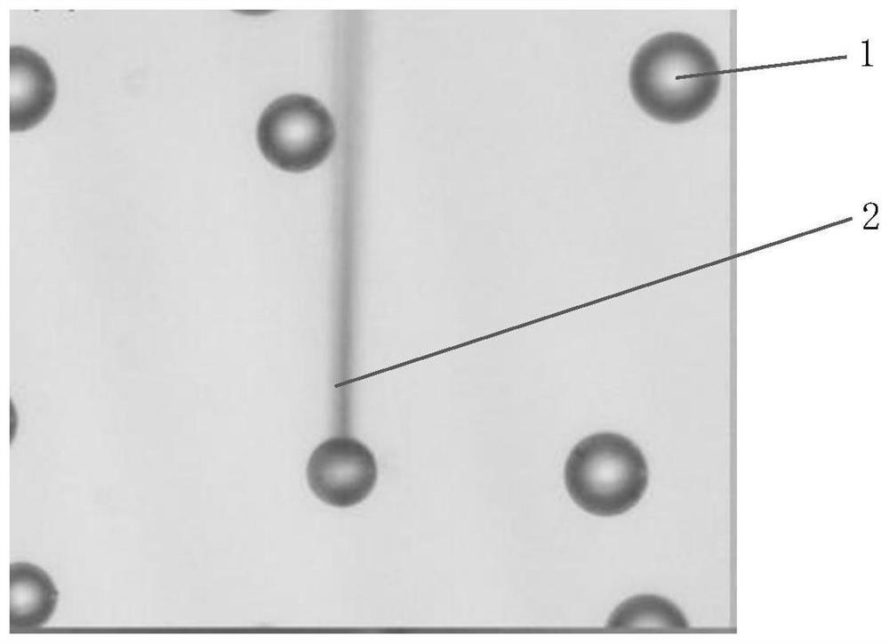
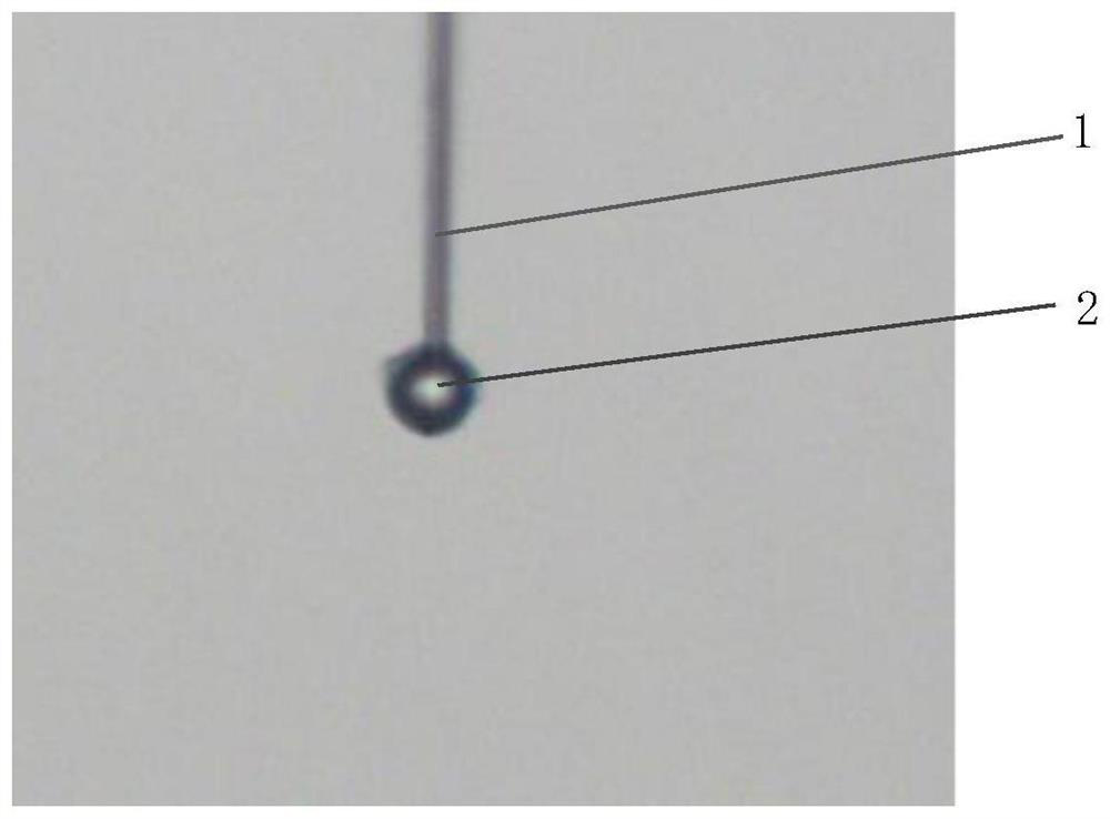
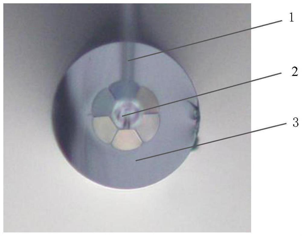
[0041] Step 1. Treat one end of the optical fiber with a selective filling method based on polystyrene microspheres and paraffin oil. First, take a microstructured optical fiber of appropriate length, remove the coating layer from both ends and cut the end face to be flat, and place it vertically under the microscope for use. At the same time, polystyrene microspheres 1 were sprinkled on the glass slide and placed on the microscope stage. After that, the polystyrene microspheres are operated by using the taper-drawing capillary probe 2 as a tool. The taper-drawing capillary probe can be drawn by the fiber-optic fusion taper-drawing machine, and t...


PUM

PropertyMeasurementUnit
viscosityaaaaaaaaaa

Abstract

The invention relates to a method for manufacturing an optical fiber optical fluid channel. The method comprises the following steps of: 1, manufacturing a port at one end of a fluid channel at one end of a microstructure optical fiber by utilizing a selective filling method based on polystyrene microspheres and paraffin oil; and 2, under the condition that one end of the microstructure optical fiber is ventilated, the other end of the optical fiber, except for the port of the corresponding fluid channel, is blocked by using ultraviolet curing glue, and the port of the other end of the fluid channel is manufactured. On the basis that polystyrene microspheres and paraffin oil are combined to process one end of an optical fiber, the paraffin oil is utilized to connect the optical fiber with a syringe needle, and air is slowly injected into the optical fiber while the other end of the optical fiber is immersed in an ultraviolet curing adhesive with lower viscosity. And then the end is irradiated by an ultraviolet lamp, so that the air holes at the same positions of the end and the other end can be opened and closed, and the other air holes can be closed, thereby completing the manufacturing of the fluid channel in the optical fiber.

Description

technical field [0001] The invention belongs to the technical field of optofluidic microcavity laser production, and particularly relates to a fabrication method of an optical fiber optofluidic channel. Background technique [0002] Optofluidic microcavity laser is an emerging miniaturized laser that combines optofluidic technology and microresonator. It has the advantages of compact structure, easy integration and low energy consumption. It is often used in lab-on-a-chip, optical Fluidics sensors, integrated optical systems, etc. On this basis, researchers combined bioluminescent materials with optofluidic microcavity lasers to propose optofluidic biolasers, and developed a series of applications in the analysis of DNA, peptides, cells and other biological materials. means of biochemical detection. With the maturity of microstructured fiber drawing technology, the various quartz wall structures embedded in microstructured fibers can be used as high-quality microcavities t...

Claims


Application Information

Patent Timeline
Patent Type & Authority Applications(China)
IPC IPC(8): G02B6/02H01S3/067G01D5/353
CPCG02B6/02295H01S3/06708G01D5/353
Inventor 于杰陈馨刘伯晗左文龙于洪宇
Owner TIANJIN NAVIGATION INSTR RES INST
Why Eureka
Try Eureka