
High-strength steel plate processing technology

A high-strength steel plate and processing technology, applied in metal processing equipment, manufacturing tools, furnaces, etc., can solve the problem of no waste gas treatment, and achieve the effect of promoting full contact, improving treatment efficiency, and accelerating treatment efficiency.

Pending Publication Date: 2022-07-01
何大伟
View PDF2 Cites 0 Cited by
  • Summary
  • Abstract
  • Description
  • Claims
  • Application Information

AI Technical Summary

Problems solved by technology

[0004] Based on the technical problem that the exhaust gas is not treated in the existing technology, the present invention proposes a high-strength steel plate processing technology

Method used


Image

  • High-strength steel plate processing technology
  • High-strength steel plate processing technology
  • High-strength steel plate processing technology

Examples


Embodiment 1

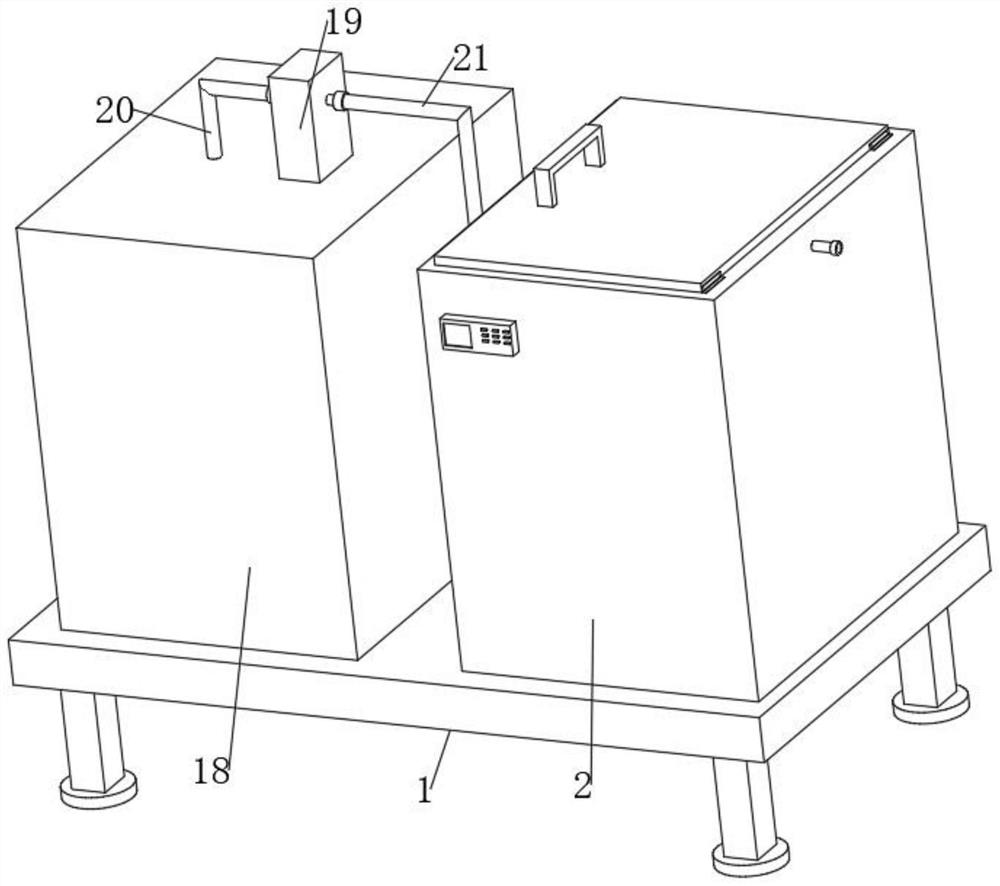
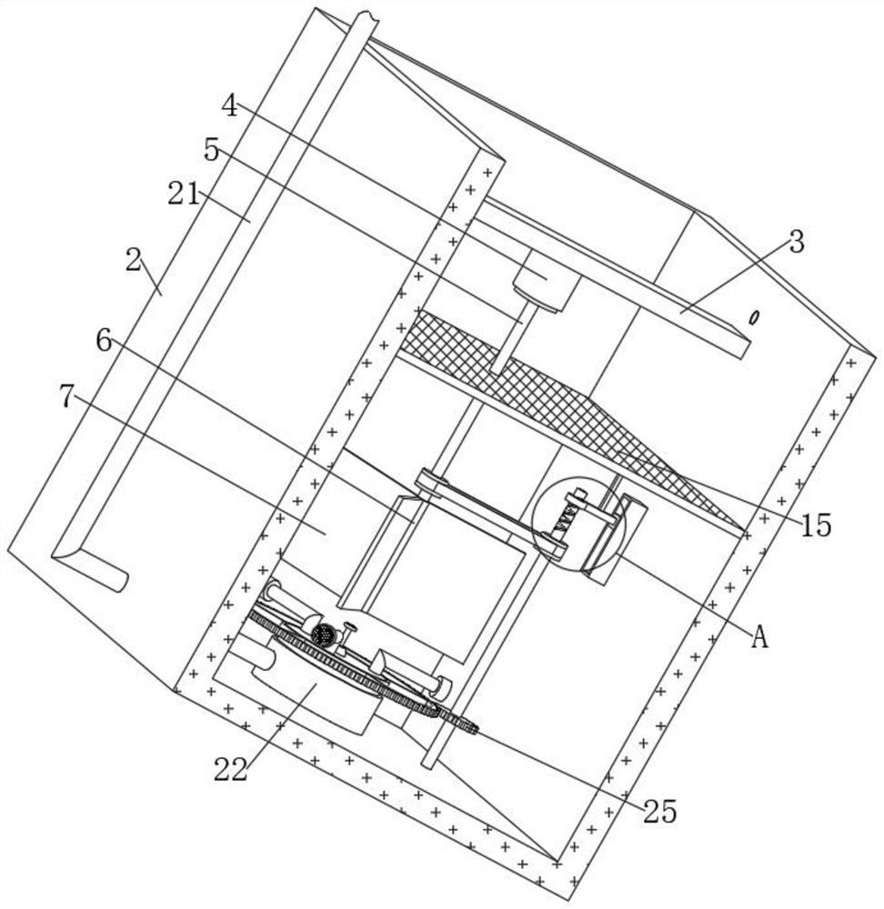
[0039] refer to Figure 1-8 , a high-strength steel plate processing technology, the processing steps are as follows:

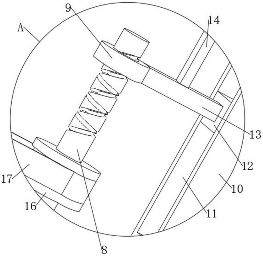
[0040] S1: place each metal raw material in the smelting equipment for smelting, adjust the internal vacuum to 0.04Pa, and pump the waste gas in the smelting box 18 through the first pipeline 20 and the second pipeline 21 into the gas accumulator 22 by the air pump 19 , and then ejected through the first air pipe 26 to form bubbles, which are fully integrated with the disinfection filtrate in the treatment box 2 to process the exhaust gas, and the output shaft of the motor 4 drives the main shaft 5, the sleeve 6 and the plurality of stirring blades 7 to rotate. , agitate the liquid and air bubbles in the treatment box 2 to speed up the exhaust gas treatment efficiency, and at the same time, through the transmission cooperation of the pulley 16 and the belt 17, the reciprocating screw 8 is rotated, and under the reciprocating thread, the reciprocating collar 9 i...

Embodiment 2

[0055] refer to Figure 1-11 , a high-strength steel plate processing technology, the processing steps are as follows:

[0056] S1: place each metal raw material in the smelting equipment for smelting, adjust the internal vacuum to 0.04Pa, and pump the waste gas in the smelting box 18 through the first pipeline 20 and the second pipeline 21 into the gas accumulator 22 by the air pump 19 , and then ejected through the first air pipe 26 to form bubbles, which are fully integrated with the disinfection filtrate in the treatment box 2 to process the exhaust gas, and the output shaft of the motor 4 drives the main shaft 5, the sleeve 6 and the plurality of stirring blades 7 to rotate. , agitate the liquid and air bubbles in the treatment box 2 to speed up the exhaust gas treatment efficiency, and at the same time, through the transmission cooperation of the pulley 16 and the belt 17, the reciprocating screw 8 is rotated, and under the reciprocating thread, the reciprocating collar ...


PUM


Abstract

The invention belongs to the technical field of steel plate machining, and particularly relates to a high-strength steel plate machining process which comprises the following machining steps: S1, placing metal raw materials in smelting equipment, pumping waste gas into a gas gathering cylinder by a gas pump, spraying the waste gas through a first gas pipe, driving stirring blades to rotate by an output shaft of a motor, and rotating a reciprocating screw rod through transmission cooperation of a belt wheel and a belt, the screen plate is driven to move up and down to refine bubbles; s2, the alloy solution is put into a casting ladle, microalloying treatment is conducted, the alloy solution is poured into a casting mold, and a steel plate blank is obtained; s3, the steel plate blank is put into a heating furnace to be heated, and finally the steel plate blank is cooled to the room temperature; s4, heating the steel plate blank to 540-560 DEG C, carrying out primary tempering, then heating the steel plate blank to 725-740 DEG C, and carrying out secondary tempering; and S5, the steel plate blank is polished and ground. According to the device, through power of the motor, the upper stirring part and the screen plate move up and down, bubbles are refined, and the bubble treatment efficiency is improved.

Description

technical field [0001] The invention relates to the technical field of steel plate processing, in particular to a high-strength steel plate processing technology. Background technique [0002] Steel is a general term for iron-carbon alloys with a carbon content between 0.02% and 2.11% by mass. The chemical composition of steel can vary greatly. Steel containing only carbon elements is called carbon steel (carbon steel) or ordinary steel; in actual production, steel often contains different alloying elements according to different uses, such as: manganese, Nickel, Vanadium, etc. The application and research of steel has a long history, but until the invention of the Bainian steelmaking method in the 19th century, the production of steel was a high-cost and low-efficiency work. Today, steel has become one of the most used materials in the world with its low price and reliable performance. It is an indispensable component in the construction industry, manufacturing industry a...

Claims


Application Information

Patent Timeline
Patent Type & Authority Applications(China)
IPC IPC(8): C22C33/04B22D1/00B24B29/00C21C7/00C21D6/00C21D9/00
CPCC22C33/04C21C7/0006B22D1/00C21D6/00C21D9/0081B24B29/00Y02P10/20
Inventor 何大伟
Owner 何大伟
Learn More