Solar power generation component manufacturing device

A technology for manufacturing devices and components, applied in the field of solar power generation components manufacturing devices, can solve the problems of casting groove processing, difficult assembly, large depth, etc., and achieve the effects of stable and reliable processing, good sandblasting effect, and simple process

Pending Publication Date: 2022-06-03
江苏中清光伏科技有限公司
View PDF14 Cites 0 Cited by
  • Summary
  • Abstract
  • Description
  • Claims
  • Application Information

AI Technical Summary

Problems solved by technology

For heatsink housings with a high number of profiled fins (refer to figure 1 ) for processing, two processing techniques are generally used, one is: the radiator shell and heat sink are independently molded and processed, and then the two are assembled. The biggest problem of this method is the difficulty of assembly. The radiator shell is not a one-piece structure, the heat transfer efficiency is not good, and the heat dissipation effect is not very good
[0003] The second is to use the integrated casting of the radiator shell and the heat sink, but this processing method has relatively high requirements for the casting mold. This type of mold (refer to figure 2 ) are generally high-hardness metal workpieces or alloy workpieces. Due to the large number of casting grooves used for casting heat sinks, the depth is large, and the thickness is small, it is difficult to process these casting grooves by traditional machining, and traditional processing methods cannot meet the requirements. Processing requirements

Method used


Image

  • Solar power generation component manufacturing device
  • Solar power generation component manufacturing device
  • Solar power generation component manufacturing device

Examples


Embodiment 1

[0045] In this embodiment, a manufacturing process for solar power generation components is proposed, which includes the following steps:

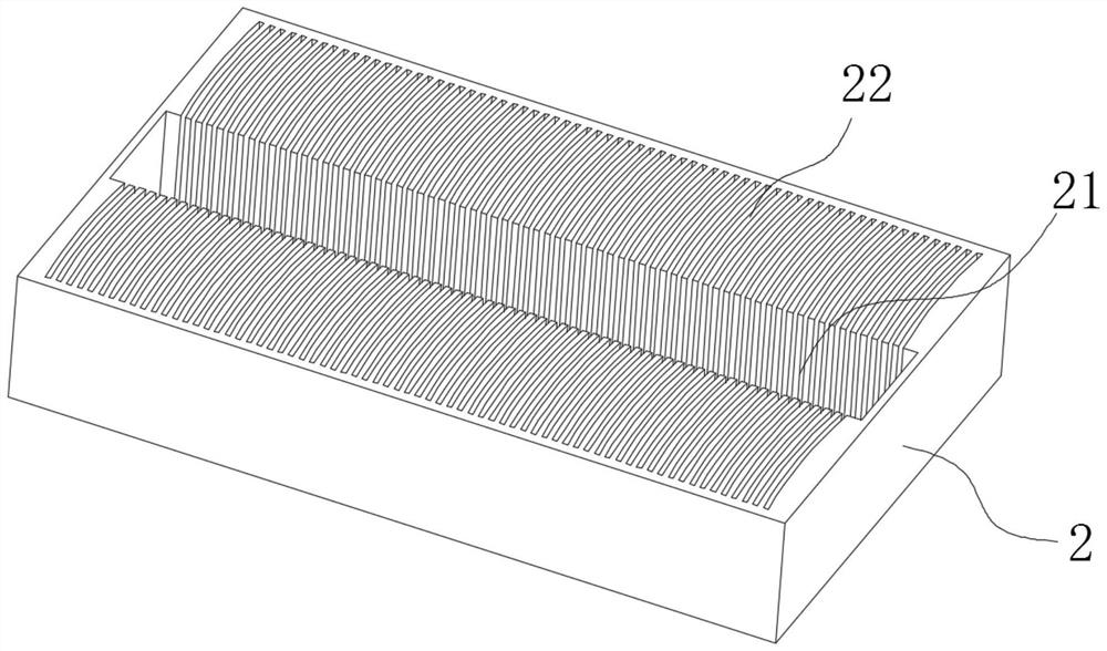
[0046] S1: First use mechanical processing, arrange the mold 2 to be processed on the milling machine, use the milling machine to process, and mill the cavity 21. The structure of the mold 2 refers to figure 2 ;

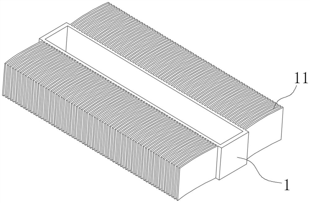
[0047] S2: Prepare the tool electrode 200. The tool electrode 200 is made of one or both of copper, graphite and copper-tungsten alloy. The structure of the tool electrode 200 is the same as that of the radiator shell 1. Etching processing, the casting grooves 22 for forming the heat sink 11 are machined on both sides of the cavity 21, and the structure of the heat sink shell 1 refers to figure 1 ;

[0048] S3: Use high-speed sand flow to blast the inner wall of the cavity 21 and the inner wall of the casting groove 22 to improve the cleanliness and roughness of the inner wall of the cavity 21 and the inner wall of the casting...

Embodiment 2

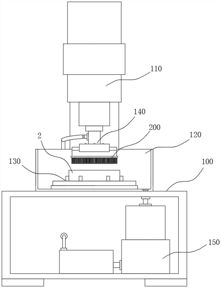
[0051] refer to image 3 , in this embodiment, a solar power generation component manufacturing device is proposed, which includes a frame 100 and a lifting mechanism 110. The lower end of the lifting mechanism 110 is equipped with an electrode chuck 140, and the electrode chuck 140 is used to clamp the tool anode 200, the tool The electrode 200 is arranged horizontally, the frame 100 is equipped with a water tank 120, the water tank 120 is arranged below the lifting mechanism 110, the water tank 120 is arranged horizontally, and a fixture 130 is installed at the bottom of the water tank 120, and the fixture 130 is used for clamping the mold 2 to be processed, the mold 2 The position corresponds to the position of the tool anode 200. The mold 2 has a cavity 21 in the middle. The mold 2 is in a state in which the cavity 21 is opened in the water tank 120 and is horizontally arranged. The length direction of the tool electrode 200 is consistent with the length direction of the mo...

Embodiment 3

[0062] refer to Figure 4 to Figure 7 , in this embodiment, a process for preparing tool electrodes is proposed, including the following steps:

[0063] S21: Preparation of connecting plate 220:

[0064] 1): First, the selected conductive material is processed into a board with a preset size, then the two sides of the board are smoothed, and the two sides of the board are recorded as the A board surface and the B board surface respectively. Mounting grooves 224 for mounting the fins 210 are milled on the surface of the A board in sequence. There are two rows of the mounting grooves 224. The two rows of mounting grooves 224 are spaced along the width direction of the A-board surface, and the two rows of the mounting grooves 224 are along the width of the A-board surface. The central axis in the length direction of the board surface is symmetrically distributed, each row of installation grooves 224 is arranged along the length direction of the A board surface, and the spacing b...


PUM


Abstract

The invention relates to the field of solar device manufacturing, and discloses a solar power generation component manufacturing device which comprises a rack and a lifting mechanism, an electrode chuck is installed at the lower end of the lifting mechanism and used for clamping a tool anode, a tool electrode is horizontally arranged, a water tank is installed on the rack and arranged below the lifting mechanism, and the lifting mechanism is arranged below the water tank. The water tank is horizontally arranged, a clamp is installed at the bottom of the water tank and used for clamping a die to be machined, a cavity is formed in the middle of the die, two rows of fins are arranged on the lower surface, corresponding to the die, of the tool electrode, the tool electrode is provided with liquid drainage holes in the position between the two rows of fins, and the liquid drainage holes are connected with a working liquid circulation system. According to the manufacturing device, electric corrosion forming machining can be conducted on the casting groove of the mold, the electric corrosion products can be discharged in the machining process, it is guaranteed that electric corrosion machining is conducted stably, and machining is stable and reliable.

Description

technical field [0001] The present invention relates to the field of solar device manufacturing, and more particularly, to a device for manufacturing solar power generation components. Background technique [0002] In the solar power generation equipment, the radiator is an indispensable component. With the continuous development of the current equipment, higher requirements for heat dissipation are put forward. In air-cooled heat dissipation, in order to improve the heat dissipation efficiency, the more commonly used method is to improve Heat dissipation area, in order to increase the heat dissipation area, the number and area of ​​heat sinks will be increased on the radiator shell, that is, the number of heat sinks will be increased, the distance between adjacent heat sinks will be reduced, and the heat sinks will be made into curved or S-shaped, etc. The special-shaped heat sink has improved the heat dissipation area compared with the traditional flat heat sink. For heat...

Claims


Application Information

Patent Timeline
IPC IPC(8): B23H1/04B23H5/04B23H11/00
CPCB23H1/04B23H5/04B23H11/00Y02P70/50
Inventor 王佳佳
Owner 江苏中清光伏科技有限公司
Why Eureka
Try Eureka