
Nano cutter coating and preparation method thereof

A nano-coating and cutting tool technology, applied in coatings, metal material coating processes, manufacturing tools, etc., to achieve the effects of improving the bonding strength of coatings, enhancing mechanical scarfing, and reducing radial displacement

Active Publication Date: 2022-03-08
SUZHOU UNIV
View PDF8 Cites 0 Cited by
  • Summary
  • Abstract
  • Description
  • Claims
  • Application Information

AI Technical Summary

Problems solved by technology

[0005] For this reason, the technical problem to be solved by the present invention is to overcome the problems of competition and cooperation in the prior art in the improvement of coating bonding force, hardness, toughness, thermal stability and other properties.

Method used


Image

  • Nano cutter coating and preparation method thereof
  • Nano cutter coating and preparation method thereof
  • Nano cutter coating and preparation method thereof

Examples


Embodiment 1

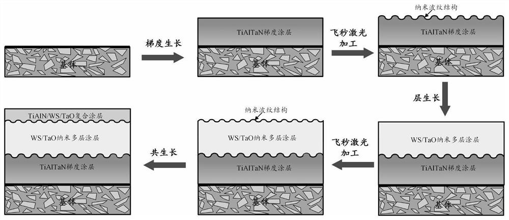
[0039] refer to figure 2 Shown, a kind of nano cutting tool coating and preparation method thereof, concrete steps are as follows:

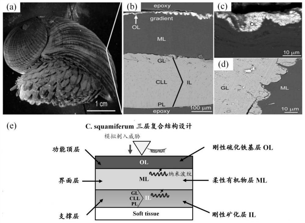
[0040] The base material of the tool is WC / Co cemented carbide, and the multi-scale bionic structure design of the tool coating is carried out in imitation of the microstructure of C. squamiferum, that is, three micron-scale layers are formed by sputtering target particle gradient growth, layer growth, and co-growth Functionally graded coatings, and introduce nanoscale corrugated structures between the interfaces of each layer to regulate the bonding strength between layers, so that the tool coating as a whole presents a "hard-tough-hard" three-layer composite structure. Its specific preparation process steps are as follows:

[0041] (1) Substrate grinding and polishing, ultrasonic cleaning: Prepare metallographic samples on the surface of the tool substrate on an automatic metallographic grinding machine, then use absolute ethanol to grind wit...

Embodiment 2

[0048] refer to figure 2 Shown, a kind of nano cutting tool coating and preparation method thereof, concrete steps are as follows:

[0049] The base material of the cutting tool is high-speed steel, and the multi-scale bionic structure design of the cutting tool coating is carried out in imitation of the microstructure of C. squamiferum, that is, a three-layer functionally graded coating at the micron scale is formed by sputtering target particle gradient growth, layer growth, and co-growth , and introduce a nanoscale corrugated structure between the interfaces of each layer to regulate the bonding strength between layers, so that the tool coating as a whole presents a "hard-tough-hard" three-layer composite structure. Its specific preparation process steps are as follows:

[0050] (1) Substrate grinding and polishing, ultrasonic cleaning: Prepare metallographic samples on the surface of the tool substrate on an automatic metallographic grinding machine, then use absolute et...


PUM


Abstract

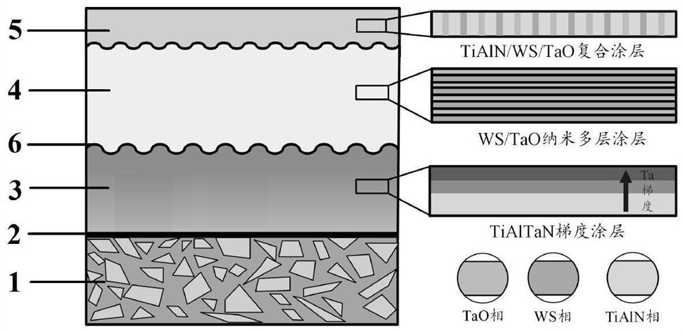
The invention relates to a nano cutter coating and a preparation method thereof, and relates to the technical field of coatings. The nanometer cutter coating comprises a cutter base body, a transition layer, a supporting layer, an interface layer and a functional top layer, wherein the transition layer, the supporting layer, the interface layer and the functional top layer are sequentially deposited on the surface of the cutter base body. The transition layer is a Ti transition layer; the supporting layer is a TiAlTaN gradient coating layer; the interface layer is a WS2 / TaO nano multi-layer coating; the functional top layer is a TiAlN / WS2 / TaO composite coating, and a nano-scale corrugated structure is introduced between interfaces of all the layers through a femtosecond laser technology to regulate and control the interlayer bonding strength, so that the whole cutter coating is of a hard-tough-hard three-layer composite structure, and multi-index collaborative optimization of mechanical properties, long-acting self-lubricating and affinity reducing functions is achieved.

Description

technical field [0001] The invention relates to the technical field of coatings, in particular to a nano-tool coating and a preparation method thereof. Background technique [0002] The laminated structure composed of carbon fiber reinforced resin matrix composites (CFRP) and titanium alloy materials has high specific strength and specific modulus. This structure is often made into key load-bearing components of aerospace vehicles through bolted connections. In order to improve the position accuracy and assembly quality of the assembly holes of the laminated structure, the laminated components must be clamped once and processed in one piece, which makes the high-efficiency and low-damage integrated hole-making technology of CFRP / titanium alloy laminated components become the field of aviation manufacturing. research hotspot. [0003] Due to its high hardness and high temperature oxidation resistance, physical vapor deposition (PVD) TiAlN-based coating tools are currently co...

Claims


Application Information

Patent Timeline
IPC IPC(8): C23C14/35C23C14/14C23C14/06B23K26/70B23K26/352
CPCC23C14/35C23C14/352C23C14/0641C23C14/14B23K26/352B23K26/702
Inventor 张克栋刘亚运刘同舜郭旭红王呈栋
Owner SUZHOU UNIV
Learn More