
Interface composite modification method of positive electrode material, positive electrode material and application

A technology of interfacial compounding and positive electrode material, applied in positive electrodes, chemical instruments and methods, nickel compounds, etc., can solve the problems of reduced discharge specific capacity rate performance, no strong chemical bonding, uneven local coating, etc. The effect of improving rate performance, improving material structure stability, and improving cycle stability

Active Publication Date: 2022-02-08
SVOLT ENERGY TECHNOLOGY CO LTD
View PDF10 Cites 0 Cited by
  • Summary
  • Abstract
  • Description
  • Claims
  • Application Information

AI Technical Summary

Problems solved by technology

The coating methods used in the prior art include wet coating and dry coating. Among them, the wet coating actually only plays the role of uniform coating, without strong chemical bonding, and the subsequent coating and firing are easy to form A small amount of partial coating is incomplete; while dry coating has higher requirements for mixing materials, once the mixing is uneven, it will lead to partial coating defects
[0005] The traditional technology has two main disadvantages: First, the side reaction between the electrolyte and the positive electrode material is mainly suppressed by surface coating, and the gas production during the battery cycle is reduced.
However, in industrial production, the surface of the positive electrode material particles is basically covered with islands or flakes, or the coating layer is relatively loose, so it is difficult to completely avoid the side reaction between the electrolyte and the positive electrode material.
Second, if the coating layer is added, the discharge specific capacity, especially the rate performance, will decrease significantly.
[0009] For the above problems, the most common solution at present is to coat the cathode material and design complex structures to improve the cycle performance and rate performance of the material, but the improvement effect is not satisfactory.

Method used

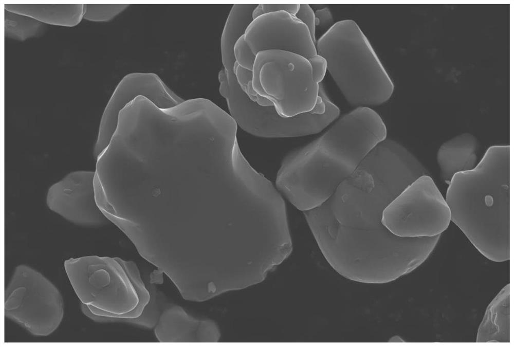
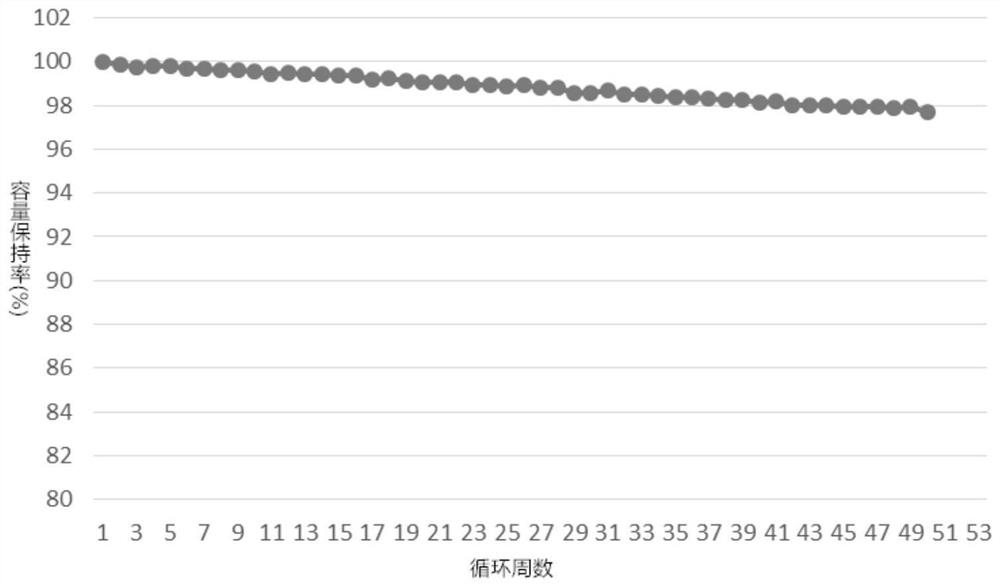
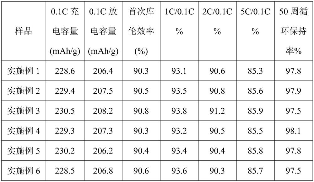

Image

  • Interface composite modification method of positive electrode material, positive electrode material and application
  • Interface composite modification method of positive electrode material, positive electrode material and application
  • Interface composite modification method of positive electrode material, positive electrode material and application

Examples


Embodiment 1

[0054] This embodiment provides a method for interfacial composite modification of nickel-cobalt lithium manganese oxide positive electrode material. The interface composite modification method specifically includes the following steps:

[0055] (Ⅰ) Precursor Ni 0.8 co 0.1 mn 0.1 (OH) 2 , Li(OH) 2 After mixing with nano zirconia for 10min once, Li(OH) 2 and the precursor according to the molar ratio of Li:(Ni+Co+Mn)=1, the addition of nano-zirconia is the precursor and Li(OH) 2 500ppm of the total mass;

[0056] (II) The material after primary mixing is placed in an oxygen atmosphere (oxygen concentration ≥ 99.99%) with an oxygen flow rate of 5L / min, heated to 800°C at a heating rate of 2°C / min, kept for 15h, and sintered after sieving;

[0057] (Ⅲ) The sintered material, cyanuric acid and boric acid were mixed for 10 minutes according to the mass ratio of 1:0.2:0.3, and then placed in a nitrogen atmosphere, and the temperature was raised to 300°C at a heating rate of 2°...

Embodiment 2

[0059] This embodiment provides a method for interfacial composite modification of nickel-cobalt lithium manganese oxide positive electrode material. The interface composite modification method specifically includes the following steps:

[0060] (Ⅰ) Precursor Ni 0.82 co 0.08 mn 0.1 (OH) 2 , Li(OH) 2 After mixing with nano-titanium oxide for 14min once, Li(OH) 2 According to the mol ratio of Li:(Ni+Co+Mn)=1.05 feeding intake with the precursor, the addition of nano-titanium oxide is the precursor and Li(OH) 1000ppm of the total mass;

[0061] (II) The materials mixed once are placed in an oxygen atmosphere (oxygen concentration ≥ 99.99%) with an oxygen flow rate of 8L / min, heated to 830°C at a heating rate of 2.5°C / min, kept for 13h, and sintered after sieving;

[0062] (Ⅲ) The sintering material, dicyandiamide and boron oxide were mixed for 14 minutes according to the mass ratio of 1:0.4:0.3, and then placed in a nitrogen atmosphere, and the temperature was raised to 380°...

Embodiment 3

[0065] This embodiment provides a method for interfacial composite modification of nickel-cobalt lithium manganese oxide positive electrode material. The interface composite modification method specifically includes the following steps:

[0066] (Ⅰ) Precursor Ni 0.85 co 0.05 mn 0.1 (OH) 2 , Li(OH) 2and nano tungsten oxide mixed for 18min once, Li(OH) 2 With the precursor according to the molar ratio of Li:(Ni+Co+Mn)=1.08 feed intake, the addition of nano-tungsten oxide is the precursor and Li(OH) 1500ppm of the total mass;

[0067] (II) Put the mixed material once in an oxygen atmosphere (oxygen concentration ≥ 99.99%) with an oxygen flow rate of 10L / min, raise the temperature to 860°C at a heating rate of 3°C / min, keep it warm for 10h, and sinter the material after sieving;

[0068] (Ⅲ) The sintering material, hydroxyethyl urea and boric acid were mixed for 18 minutes according to the mass ratio of 1:0.5:0.4, and then placed in an argon atmosphere, and the temperature wa...


PUM

PropertyMeasurementUnit
particle sizeaaaaaaaaaa
specific surface areaaaaaaaaaaa

Abstract

The invention provides an interface composite modification method of a positive electrode material, the positive electrode material and application, and the interface composite modification method comprises the following steps: mixing a precursor, a lithium source and a nano oxide for the first time, conducting calcining to obtain a sintered material, mixing the sintered material, an inducer and a boron source for the second time, and conducting calcining to obtain a single crystal positive electrode material. According to the interface composite modification method provided by the invention, the content of residual alkali on the surface of the positive electrode material is reduced in a co-coating manner, so that the cycling stability, the rate capability and the thermal stability of the positive electrode material are improved.

Description

technical field [0001] The invention belongs to the technical field of positive electrode materials, and relates to an interface composite modification method of positive electrode materials, positive electrode materials and applications. Background technique [0002] At present, with the rapid development of the new energy automobile industry, there are higher requirements for the energy density and power density of lithium-ion batteries. The positive electrode material is one of the most critical materials for improving the energy density of lithium-ion batteries. Therefore, the preparation of high specific capacity Cathode materials have become a current research hotspot. The ternary layered positive electrode material has the advantages of higher discharge specific capacity, better cycle performance and lower cost, and with the increase of Ni content, the discharge specific capacity gradually increases, when the Ni content increases only by more than 80% , the discharge...

Claims


Application Information

Patent Timeline
Patent Type & Authority Applications(China)
IPC IPC(8): C01G53/00H01M4/36H01M4/505H01M4/525H01M4/62H01M10/052H01M10/0525
CPCC01G53/44H01M4/366H01M4/505H01M4/525H01M4/628H01M10/052H01M10/0525C01P2004/01C01P2006/40H01M2004/021H01M2004/028Y02E60/10
Inventor 张树涛李子郯王壮马加力王亚州白艳杨红新
Owner SVOLT ENERGY TECHNOLOGY CO LTD
Learn More