Triangular shaft sleeve machining method

A processing method and triangular shaft technology, applied in the direction of shaft couplings, rigid shaft couplings, mechanical equipment, etc., can solve the problem of low alignment accuracy, large vibration of the whole machine, and inability to ensure the coaxiality of the inner hole and the outer circle degree requirements etc.

Pending Publication Date: 2021-12-21
CHONGQING JIANGJIN SHIPBUILDING IND
View PDF9 Cites 0 Cited by
  • Summary
  • Abstract
  • Description
  • Claims
  • Application Information

AI Technical Summary

Problems solved by technology

The ultra-long precision special-shaped hole in the inner hole of the triangular bushing has high requirements for roughness and geometric tolerance accuracy. Combined with the machining performance and design requirements of the material itself, the processing method is greatly restricted, and the conventional process plan is difficult. Guaranteed Design Requirements
If the roughness and shape and position tolerance requirements cannot be controlled, it will lead to large vibration of the whole machine, short life, low efficiency, and even safety accidents
[0004] This part has the following difficulties in the existing manufacturing scheme; 1. The material of the triangular bushing is 45CrNiMoVA, which is a low-alloy ultra-high-strength steel and requires a hardness of HRC40-44. Compared with milling, it is easy to cause tool wear. As a result, the machining results are unstable, and finally the requirements for the wear resistance of the machining tools are high; 2. The length-to-diameter ratio at the inner hole reaches 3:1, and the rigidity of the tool system in the milling process is difficult to meet the accuracy requirements; 3. The roughness and The precision of shape and position tolerance is high, which is difficult to meet by conventional milling; the special-shaped hole structure at the inner hole cannot be realized by conventional grinding, which puts forward new requirements for the formulation of processing plan
4. The alignment accuracy is low, and the coaxiality requirements of the inner hole and the outer circle cannot be guaranteed

Method used


Image

  • Triangular shaft sleeve machining method
  • Triangular shaft sleeve machining method
  • Triangular shaft sleeve machining method

Examples


Embodiment Construction

[0050] Embodiments of the present invention are described in detail below, examples of which are shown in the drawings, wherein the same or similar reference numerals designate the same or similar elements or elements having the same or similar functions throughout. The embodiments described below by referring to the figures are exemplary and are intended to explain the present invention and should not be construed as limiting the present invention.

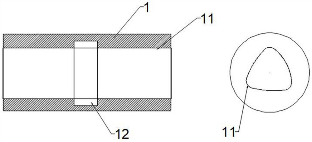
[0051] see Figure 1 to Figure 14 , the present invention provides a processing method of a triangular bushing: the triangular bushing 1 includes a special-shaped hole 11 and a circular hole 12, the circular hole 12 is located in the middle of the special-shaped hole 11, here the special-shaped hole 11 is Taking the triangular hole as an example, the processing method of the triangular bushing 1 includes:

[0052] S101 obtains the test rod and detects it;

[0053] The specific steps are:

[0054] S201 illuminates the surface o...


PUM


Abstract

The invention relates to the field of machine tool machining, in particular to a triangular shaft sleeve machining method. The method comprises the steps that a test bar is obtained and detected; an inner circular hole of the test bar is machined; heat treatment is conducted on the machined test bar; semi-finish turning is conducted on a large outer circle and the inner circular hole; the test bar is clamped by adopting a first tool, and finish machining is conducted on the outer circle and two end surfaces of the test bar; and the test bar is clamped by adopting a second tool, and a special-shaped hole is cut through low-speed wire cutting. Before manufacturing, the quality of the test bar is detected, then the inner circular hole is machined to remove redundant allowance, then heat treatment is conducted to improve strength and reduce deformation, then semi-finish turning and finish machining are conducted to guarantee the machining quality, low-speed wire cutting and electric discharge machining are adopted, parts are not contacted, and the machining quality can be better controlled by means of the precision of equipment.

Description

technical field [0001] The invention relates to the field of machine tool processing, in particular to a processing method for a triangular bushing. Background technique [0002] The triangular bushing is the key part of this type of turbine product, which plays a role in transmitting torque during the operation of the machine. Such as figure 1 shown. [0003] The triangular bushing is installed on the main shaft, and matches the special-shaped hole on the main shaft through the ultra-long precision special-shaped hole in the inner hole, and plays the role of transmitting torque and power by utilizing the fitting area and matching accuracy between the special-shaped holes. The ultra-long precision special-shaped hole in the inner hole of the triangular bushing has high requirements for roughness and geometric tolerance accuracy. Combined with the machining performance and design requirements of the material itself, the processing method is greatly restricted, and the conve...

Claims


Application Information

Patent Timeline
Patent Type & Authority Applications(China)
IPC IPC(8): B23P15/00F16D1/08
CPCB23P15/00F16D1/08
Inventor 李成科蒋中亮柯益杨川华杨意松周德贵
Owner CHONGQING JIANGJIN SHIPBUILDING IND
Why Eureka
Try Eureka