
Circular seam milling and friction stir welding integrated device for aluminum alloy storage tank

A technology of friction stir welding and aluminum alloy, which is applied in the direction of milling machine equipment, welding equipment, non-electric welding equipment, etc., can solve the problem of high working axis, difficult operation of workers, and poor guarantee of welding quality between mechanisms and other problems, to achieve the effect of reducing the working height, increasing the practicality, ensuring the quality of milling processing and welding quality

Inactive Publication Date: 2021-12-17
GUIZHOU AEROSPACE TIANMA ELECTRICAL TECH
View PDF7 Cites 2 Cited by
  • Summary
  • Abstract
  • Description
  • Claims
  • Application Information

AI Technical Summary

Problems solved by technology

The former has great advantages for welding small-size products, but the problems of moment of inertia and inter-mechanism synchronization caused by the rotation of large-size products with super large diameter and long length make the welding quality not well guaranteed. It is easy to be damaged; the latter is due to the movement of the gantry and the inability of the gantry foundation to sink, resulting in a higher working axis, which brings difficulties for workers to operate and poor operating safety. There is no good technical solution in the prior art to solve the problem. this problem

Method used


Image

  • Circular seam milling and friction stir welding integrated device for aluminum alloy storage tank
  • Circular seam milling and friction stir welding integrated device for aluminum alloy storage tank
  • Circular seam milling and friction stir welding integrated device for aluminum alloy storage tank

Examples


Embodiment Construction

[0034] The following will clearly and completely describe the technical solutions in the embodiments of the present invention with reference to the accompanying drawings in the embodiments of the present invention. Obviously, the described embodiments are only some of the embodiments of the present invention, not all of them. Based on the embodiments of the present invention, all other embodiments obtained by persons of ordinary skill in the art without creative efforts fall within the protection scope of the present invention.

[0035] It should be noted that all directional indications (such as up, down, left, right, front, back...) in the embodiments of the present invention are only used to explain the relationship between the components in a certain posture (as shown in the accompanying drawings). Relative positional relationship, movement conditions, etc., if the specific posture changes, the directional indication will also change accordingly.

[0036] In addition, the ...


PUM


Abstract

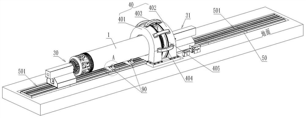
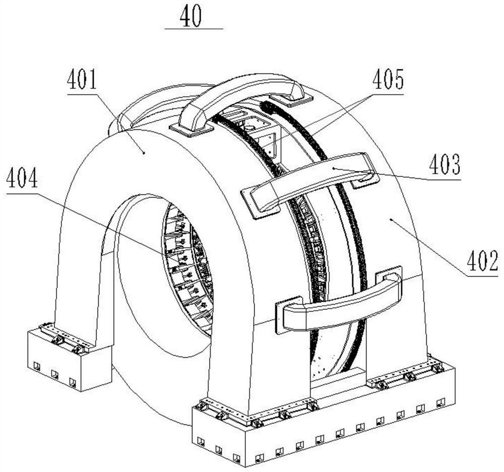
The invention discloses a circular seam milling and friction stir welding integrated device for an aluminum alloy storage tank. The circular seam milling and friction stir welding integrated device comprises a friction stir welding machine head and a milling machine head and further comprises an annular gantry, a lathe bed, a headstock and a tailstock. The annular gantry is arranged in the middle of the lathe bed. Transmission sliding rails are arranged at the positions, on the two sides of the annular gantry, of the lathe bed. The headstock and the tailstock are installed on the transmission sliding rails on the two sides of the annular gantry correspondingly. A swing mechanism is arranged on the annular gantry, and the friction stir welding machine head and the milling machine head are installed on the swing mechanism. When the circular seam milling and friction stir welding integrated device is used for carrying out circular seam milling and friction stir welding on the aluminum alloy storage tank, a workpiece is mounted on the headstock and the annular gantry as well as the tailstock and the annular gantry, the workpiece does not need to rotate, the friction stir welding machine head and the milling machine head rotate around the workpiece through the swing mechanism to carry out milling machining or welding machining, the problem of device abrasion or precision reduction caused by large inertia brought by workpiece rotation is avoided, and the milling machining quality and the welding quality are guaranteed.

Description

technical field [0001] The invention relates to the technical field of mechanical processing equipment, in particular to an integrated device for milling the circumferential seam of an aluminum alloy storage tank and friction stir welding. Background technique [0002] In recent years, with the development of aerospace technology, there is an urgent need for efficient and rapid manufacturing of large-size aluminum alloy cylinders. Compared with fusion welding, friction stir welding has higher welding strength, less welding deformation, and is greener. It can be applied to the manufacture of storage tanks. [0003] Friction stir welding has been hailed as the most creative invention in the welding field for 30 years. It is a high-quality, efficient, green, low-cost, and low-distortion solid-phase welding method that completely solves the problems caused by welding of various non-ferrous metals. A series of problems, and gradually replaced the fusion welding method, has been ...

Claims


Application Information

Patent Timeline
Patent Type & Authority Applications(China)
IPC IPC(8): B23P23/04B23C3/00B23K20/12
CPCB23P23/04B23C3/00B23K20/12
Inventor 符书豪戈军委刘邦森王聂龙姚君山覃广林张伟赵源马文融
Owner GUIZHOU AEROSPACE TIANMA ELECTRICAL TECH
Learn More