
a transformer

A technology of transformers and fixers, applied in the field of transformers, can solve the problems of small contact area between fins and heat, heat cannot be quickly diffused, and reduce the heat dissipation effect of fins, so as to improve the effect of heat dissipation and the effect of receiving heat , Improve the cooling effect

Active Publication Date: 2021-11-16
NANTONG HAIWANG ELECTRIC
View PDF3 Cites 1 Cited by
  • Summary
  • Abstract
  • Description
  • Claims
  • Application Information

AI Technical Summary

Problems solved by technology

[0004] When some existing transformers are working, their internal working parts will generate a lot of heat, and the traditional heat dissipation method is realized by using fins. However, the contact area between the traditional fins and heat is too small, and the heat conduction efficiency is poor, so that The heat dissipation effect is not good, and the contact effect between the inside and the outside air of the traditional transformer is too poor, so the internal heat cannot be dissipated quickly. In addition, because the transformer has been placed outdoors, the fins will be damaged during long-term use. A large amount of debris is easy to adhere to the surface, which reduces the heat dissipation effect of the fins

Method used


Image

  • a transformer
  • a transformer
  • a transformer

Examples


Embodiment 1

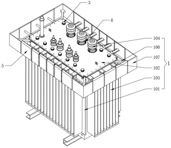
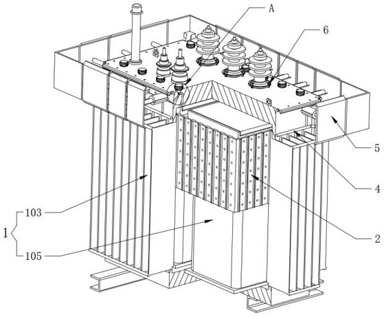
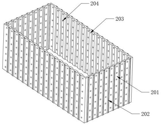
[0046] see figure 1 , 2 , a transformer, comprising, a transformer 1, a heat spreader 2 and a pneumatic cooling mechanism 3;

[0047] refer to figure 1 as well as figure 2, the transformer 1 also includes an outer body 101, an inner core 105 is fixedly installed inside the outer body 101, and the inner core 105 completes the work of voltage transformation after power-on, and the four side walls of the outer body 101 are fixedly provided with fin plates 103, and The main function of 103 is to dissipate heat. The top of the outer body 101 is fixedly assembled with a top board 102. The top board 102 is used to provide installation space for various wiring components and other circuit components. The upper surface of the top board 102 is equidistantly assembled with The terminal 104 and the four corners of the top board 102 are fixedly welded with side frame rods 106, and the other ends of the four side frame rods 106 are fixedly welded with corner guards 107, and the corner g...

Embodiment 2

[0053] see Figure 5 , 6 , a transformer, comprising, a gap clearing structure 4 and a multifunctional anti-shock structure 5;

[0054] refer to Figure 5 and Figure 6 The top outer wall of the outer body 101 is provided with a gap clearing structure 4, the gap clearing structure 4 also includes a main air pipe 401, the main air pipe 401 is fixedly sleeved on the top outer wall of the outer body 101, and the lower surface of the main air pipe 401 is equidistantly fixedly connected with an air jet pipe 402, A single air jet tube 402 is respectively arranged in the space between the fin plates 103 , and one air jet tube 402 is set in every space between two fin plates 103 .

[0055] refer to Figure 6 and Figure 7 , the multi-functional anti-collision structure 5 also includes an outer tube 501, which is equidistant and fixedly installed on the top of the outer wall of the outer body 101, and an inner rod 503 is movably installed inside the outer tube 501, and one end of ...

Embodiment 3

[0058] see Figure 8 and Figure 9 , a transformer, comprising, a terminal holder 6;

[0059] refer to Figure 8 and Figure 9 , the terminal holder 6 is sleeved on the bottom end of the outer surface of the terminal 104, the terminal holder 6 also includes a lifting ring 604, the bottom edge of the terminal 104 is equidistantly equipped with a swivel 601, and the inside of the swivel 601 is connected by rotation. There is a clamping rod 602, the bottom end of the clamping rod 602 can be rotated with the body 601 as the center of a circle, the top of the clamping rod 602 is fixedly equipped with a clamping block 603, the inside of the clamping rod 602 is fixed with a guide groove 605, and the inner wall of the lifting ring 604 is equidistant Embedded with embedded rods 606, the embedded rods 606 are movably arranged inside the guide groove 605, and the inner wall of the top of the guide groove 605 is fixedly provided with a block 607, and the lifting ring 604 is manually li...


PUM


Abstract

The invention discloses a transformer, which belongs to the field of electric equipment. A transformer includes a transformer, a heat conductor, a pneumatic heat dissipation mechanism, a multifunctional anti-impact structure and a terminal holder. The heat conduction plate is movably sleeved in the inner machine The outer surface of the core, one end of the fin plate is stuck inside the fin plate groove, and the inner edge of the top machine plate is equidistantly provided with a lead-out pipe and an air guide pipe, and the swivel base is fixedly installed on the The top of the lead-out pipe, the inside of the outer pipe is equipped with an inner rod, and one end of the inner rod is fixedly welded with a crash plate, and the terminal holder is sleeved on the bottom end of the outer surface of the terminal. It can quickly guide the heat to the fin plate and directly introduce the hot air into the atmosphere; in addition, it not only has the characteristics of anti-collision and shock absorption, but also can use the impact force to achieve the effect of cleaning the fin; finally, it improves the safety of the terminal post when it is in use. Stability, and the reinforcement operation is simpler and faster.

Description

technical field [0001] The present invention relates to the field of electric equipment, and more specifically, relates to a transformer. Background technique [0002] A transformer (Transformer) is a device that uses the principle of electromagnetic induction to change the AC voltage. The main components are the primary coil, the secondary coil and the iron core (magnetic core); the transformer is a power transformer whose operating frequency exceeds the intermediate frequency (10kHz), mainly used for It is used as a high-frequency switching power supply transformer in high-frequency switching power supplies, and is also used as a high-frequency inverter power supply transformer in high-frequency inverter power supplies and high-frequency inverter welding machines; [0003] However, existing transformers have the following disadvantages: [0004] When some existing transformers are working, their internal working parts will generate a lot of heat, and the traditional heat ...

Claims


Application Information

Patent Timeline
Patent Type & Authority Patents(China)
IPC IPC(8): H01F27/22H01F27/08H01F27/02H01F27/29B01D46/10F16F15/067B08B5/02
CPCH01F27/22H01F27/085H01F27/022H01F27/29B01D46/10F16F15/067B08B5/02
Inventor 石明鑫
Owner NANTONG HAIWANG ELECTRIC
Learn More