
Chip wafer-level packaging structure of micro electro mechanical system and manufacturing process of chip wafer-level packaging structure

A micro-electro-mechanical system and wafer-level packaging technology, which is applied in the direction of micro-structure technology, micro-structure devices, and manufacturing micro-structure devices, can solve the problems that affect the performance of micro-electro-mechanical systems, can not effectively reduce the impact of packaging stress, Young's modulus and Problems such as thermal expansion coefficient mismatch

Pending Publication Date: 2021-09-28
INST OF GEOLOGY & GEOPHYSICS CHINESE ACAD OF SCI +1
View PDF22 Cites 0 Cited by
  • Summary
  • Abstract
  • Description
  • Claims
  • Application Information

AI Technical Summary

Problems solved by technology

However, if the wafer-level packaged MEMS chip is soldered to the circuit board by flip-chip ball bonding technology, there will also be a mismatch between the Young's modulus and the thermal expansion coefficient between the circuit board and the chip.
At the same time, external stress can also be transmitted to the MEMS chip through the circuit board, causing deformation of the MEMS structure inside, greatly affecting the performance of the MEMS
Therefore, conventional wafer-level packaging technology cannot effectively reduce the impact of packaging stress on MEMS chips.

Method used


Image

  • Chip wafer-level packaging structure of micro electro mechanical system and manufacturing process of chip wafer-level packaging structure
  • Chip wafer-level packaging structure of micro electro mechanical system and manufacturing process of chip wafer-level packaging structure
  • Chip wafer-level packaging structure of micro electro mechanical system and manufacturing process of chip wafer-level packaging structure

Examples


Embodiment Construction

[0040]The present invention will be described in detail below in conjunction with the embodiments and the accompanying drawings. It should be noted that the described embodiments are only intended to facilitate the understanding of the present invention, rather than limiting it in any way.

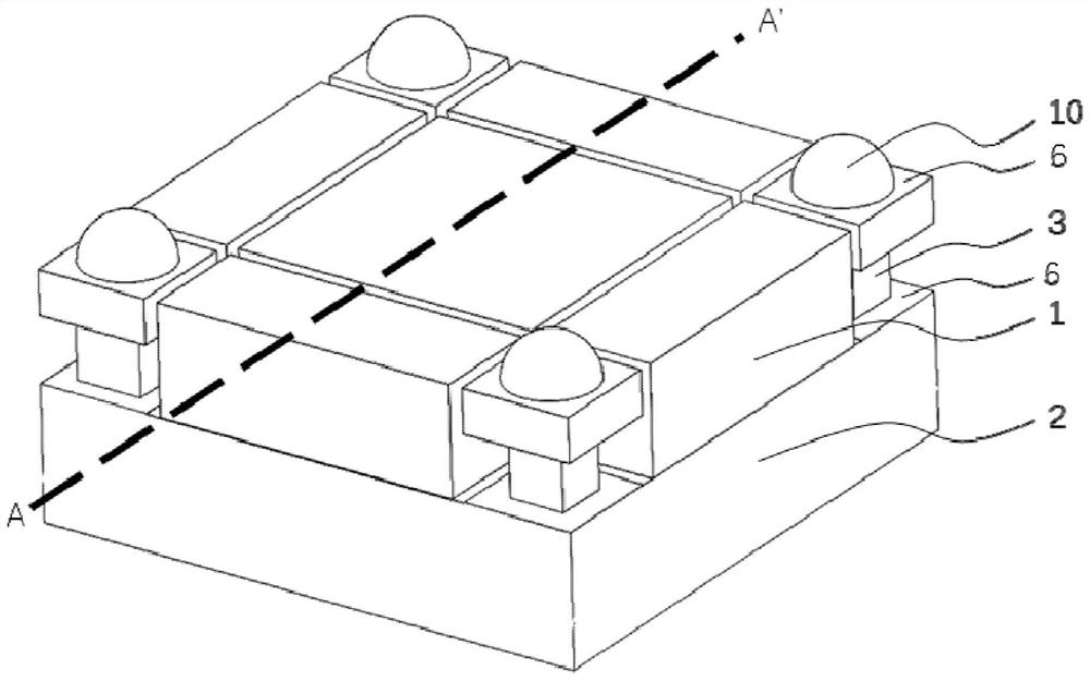
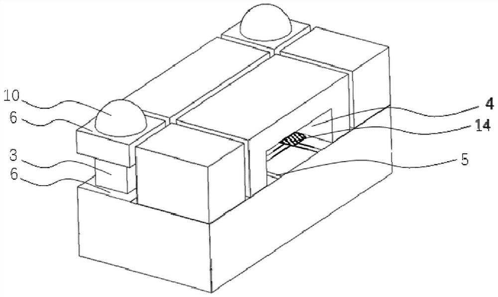
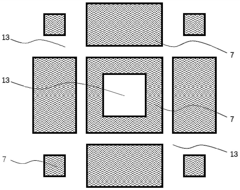
[0041] refer to figure 1 , figure 2 , according to an embodiment of a MEMS chip wafer level package provided by the present invention. In this embodiment, the cover plate 1 and the substrate 2 are bonded to each other. The cover plate 1 is usually made of monocrystalline silicon. The substrate 2 can be selected to use a single crystal silicon wafer, an SOI silicon wafer, etc. according to the final chip structure and manufacturing process. Wherein, a recessed portion 13 is formed on one side of the cover plate 1 , and a cavity is formed between the recessed portion 13 and the substrate 2 after the cover plate 1 and the substrate 2 are bonded. A plurality of micro-electromechanical ele...


PUM


Abstract

The invention relates to the field of chip wafer-level packaging, in particular to wafer-level packaging of a micro electro mechanical system chip which is easily influenced by packaging stress and a related manufacturing process of the wafer-level packaging. The wafer level packaging structure comprises a substrate and a cover plate, the substrate is a micro electro mechanical system chip to be packaged, and a concave part is formed on the cover plate. The cover plate and the substrate are bonded to form a sealed cavity, and the substrate in the cavity is provided with a micro-electro-mechanical element. The cover plate can be divided into a plurality of mutually insulated elastic electric pins through scribing. The bottom of the electric pin is smaller than the top of the electric pin, and the electric pin is of a mushroom-shaped structure and has the function of releasing packaging stress. The wafer level package can reduce the packaging stress, thereby improving the performance of the micro electro mechanical system chip. In addition, the wafer-level packaged micro-electro-mechanical system chip is smaller in size and low in packaging cost, meets the requirement of flip ball bonding, and is favorable for improving the integration level of the micro-electro-mechanical system.

Description

technical field [0001] The invention relates to chip wafer-level packaging, in particular to a micro-electromechanical system chip wafer-level packaging structure easily affected by packaging stress and a manufacturing process thereof. Background technique [0002] In the production process of integrated circuit chips, chip packaging is a very important link. Since the feature size on the chip is very small, it is difficult for the metal contacts to be directly connected to the wires on the circuit board. It is necessary to establish a connection between the contacts on the chip and the circuit board through packaging technology. In addition, in actual use, the chip generally needs to be protected to prevent accidental damage. The traditional chip packaging technology is to fix a pre-processed and divided single chip in the package shell, and electrically connect the contacts on the chip to the electrical pins on the package shell through wire bonding technology, and finall...

Claims


Application Information

Patent Timeline
Patent Type & Authority Applications(China)
IPC IPC(8): B81B7/02B81B7/00B81C1/00
CPCB81B7/0006B81B7/02B81C1/00301B81C1/00277B81B2207/07
Inventor 林德泉周显良王文
Owner INST OF GEOLOGY & GEOPHYSICS CHINESE ACAD OF SCI
Learn More