
Supported catalyst based on fiber carrier, preparation method thereof and indoor air purification device

A technology for supporting catalysts and carriers, which is applied in the field of catalyst preparation, can solve the problems of difficulty in meeting actual production needs, reduced mechanical properties, and high technical costs, and achieve the effects of promoting bonding, high loading capacity, and firm bonding

Pending Publication Date: 2021-08-24
TSINGHUA UNIV +1
View PDF6 Cites 1 Cited by
  • Summary
  • Abstract
  • Description
  • Claims
  • Application Information

AI Technical Summary

Problems solved by technology

For example, it has been reported that the MnO 2 and activated carbon particles loaded on the fiber cloth to prepare the air purification board, but the binder will cover part of the active components of the nanoparticles, inhibiting its catalytic activity
It is also reported that the SnO 2 Powder and sulfur nanoparticles were added to the electrospinning solution, and the prepared fiber membrane was cured and infiltrated into the CS 2 solution, followed by high-temperature carbonization to obtain SnO 2-x / C nanofibers, SnO 2-x Nanoparticles are highly dispersed in carbon fiber with proper void space, but the SnO in this nanofiber 2-x The nanoparticles are completely wrapped by carbon nanofibers, and the mechanical properties of the material are significantly reduced after calcination
It is also reported that polypropylene (PP) melt-blown filter material is used as the substrate, and an oxide film is formed on the surface by atomic layer deposition (ALD), and then MnO is grown in situ on the surface by hydrothermal synthesis. 2 particles, the MnO in the prepared composite 2 / Metal oxide / PP has a high content of surface active oxygen groups and particle loading fastness, but the process is complicated, and the cost of the atomic layer deposition method is high, which is difficult to meet the actual production needs

Method used


Image

  • Supported catalyst based on fiber carrier, preparation method thereof and indoor air purification device
  • Supported catalyst based on fiber carrier, preparation method thereof and indoor air purification device
  • Supported catalyst based on fiber carrier, preparation method thereof and indoor air purification device

Examples


preparation example Construction

[0028] In order to solve the problems existing in the above-mentioned prior art, an embodiment of the present invention provides a method for preparing a supported catalyst based on a fiber carrier, comprising the following steps:

[0029] placing the fiber carrier in a stirring device, adding the active ingredient in stages, and mechanically stirring once after each addition, so as to load the active ingredient on the fiber carrier;

[0030] The single mechanical stirring process is as follows: the stirring speed is 500rad / min~1500rad / min, the stirring power is 0.5kW~2.5kW, during the stirring process, there is a pause every 5s~12s, the pause time is 3s~10s, and the total stirring time is 20s ~50s, the temperature in the stirring device is kept at 25°C~80°C;

[0031] Wherein, the active ingredient is metal nanoparticles or metal oxide nanoparticles.

[0032]The preparation method of the supported catalyst based on the fiber carrier provided in the embodiment of the present i...

Embodiment 1

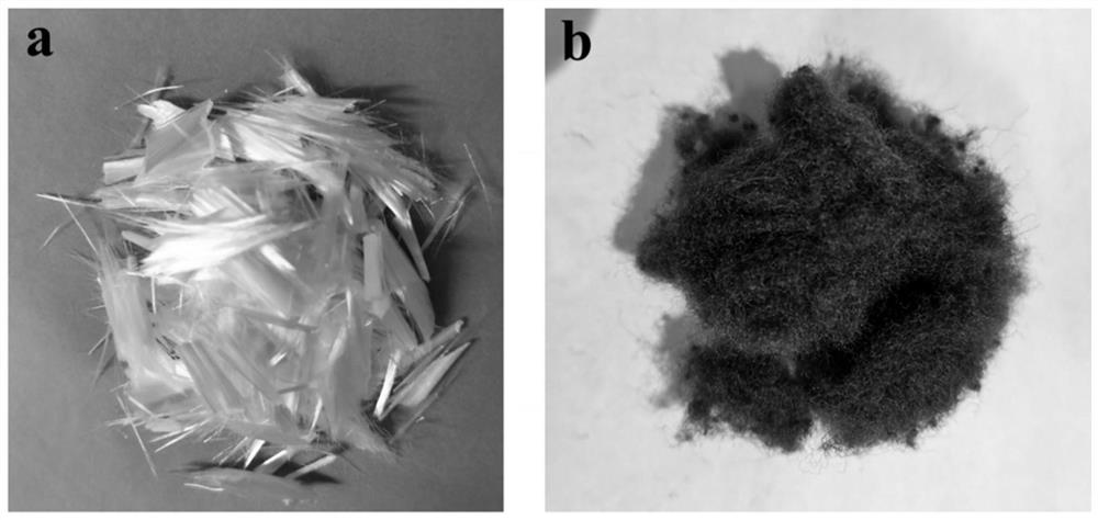
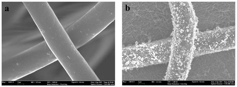
[0051] (1) Weigh 2g of polyester fiber with a diameter of 7μm, 0.3g of manganese dioxide (MnO 2 ) nanoparticles, put into a mixer, the power of the mixer is 1.5kW, and the set speed is 1500rad / min. Start the stirring device for 5s, after an interval of 3s, start again. This operation was repeated 4 times to complete the first mechanical stirring. After the stirring was finished, the temperature in the stirring device was measured to be 55°C.

[0052] (2) Unscrew the lid of the mixer and add 0.3g MnO 2 Nanoparticles, start the mixer again, and carry out the second mechanical stirring, which is the same as the first mechanical stirring operation. The power and speed of the mixer are unchanged, and the stirring device is started for 5 seconds. After an interval of 3 seconds, start again and repeat 4 times. After the stirring was finished, the temperature in the stirring device was measured to be 55°C.

[0053] (3) Repeat step (2), carry out mechanical stirring for the third t...

Embodiment 2

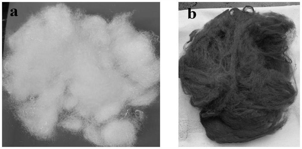
[0057] (1) Weigh 3g of viscose fiber with a diameter of 30 μm, 0.8g of tricobalt tetroxide (Co 3 o 4 ) nanoparticles, put into a mixer, the power of the mixer is 1kW, and the set speed is 1200rad / min. Start the stirring device for 10s, after a 5s interval, start again. This operation was repeated 5 times to complete the first mechanical stirring. After the stirring was finished, the temperature in the stirring device was measured to be 60°C.

[0058] (2) Unscrew the lid of the blender, add 0.8g Co 3 o 4 Nanoparticles, start the mixer again, and carry out the second mechanical stirring, which is the same as the first mechanical stirring operation. The power and speed of the mixer are unchanged, and the stirring device is started for 10 seconds. After an interval of 5 seconds, start again and repeat 5 times. After the stirring was finished, the temperature in the stirring device was measured to be 60°C.

[0059] (3) repeat step (2) 3 times, carry out mechanical stirring fo...


PUM

PropertyMeasurementUnit
Particle sizeaaaaaaaaaa
Diameteraaaaaaaaaa
Diameteraaaaaaaaaa

Abstract

The invention relates to a preparation method of a supported catalyst based on a fiber carrier, which comprises the following steps of placing the fiber carrier in a stirring device, adding active ingredients by several times, and carrying out mechanical stirring once after each time of adding so as to load the active ingredients on the fiber carrier. The single mechanical stirring process is as follows: the stirring rotating speed is 500 rad / min-1500 rad / min, the stirring power is 0.5 kW-2. 5kW, in the stirring process, the stirring is paused for each 5 s-12 s, the pause time is 3 s-15 s, the total stirring time is 20 s-50 s, the temperature in a stirring device is kept at 25 DEG C-80 DEG C, and the active component is metal nanoparticles or metal oxide nanoparticles. The invention also relates to the supported catalyst prepared by the preparation method. The invention further relates to an indoor air purification device.

Description

technical field [0001] The invention relates to the technical field of catalyst preparation, in particular to a fiber carrier-based loaded catalyst, a preparation method thereof, and an indoor air purification device. Background technique [0002] Various volatile organic pollutants (Volatile organic compounds, VOCs) such as formaldehyde and benzene series emitted by building materials, paints, furniture, etc. have caused serious harm to human health. At present, catalytic decomposition technology is considered to be a relatively effective and mature way to purify indoor pollutant gases due to its advantages of low energy consumption, energy saving, environmental protection, high efficiency and stability. Commonly used catalysts include noble metal catalysts and transition metal oxide catalysts, such as Pt, Au, Ag 2 O, MnO 2 、TiO 2 , Fe 2 o 3 , CeO 2 、Co 3 o 4 Wait. Because such catalysts exist in the form of particles, they cannot be used directly in practical appl...

Claims


Application Information

Patent Timeline
IPC IPC(8): B01J21/06B01J23/34B01J23/75B01J31/06B01J35/06B01D53/86B01D53/70B01D53/62B01D53/44
CPCB01J31/069B01J23/34B01J21/063B01J23/75B01D53/8668B01D53/8671B01D53/8687B01D2258/06B01D2257/504B01D2257/704B01D2257/708B01J35/23B01J35/58
Inventor 张彭义屈永帅
Owner TSINGHUA UNIV
Learn More