Liquid metal heating directional solidification device and casting method

A technology of directional solidification and liquid metal, applied in the field of investment precision casting, can solve the problems of low efficiency, achieve the effect of improving heat transfer efficiency and temperature gradient, and eliminating freckle defects

Pending Publication Date: 2021-06-18
深圳市万泽中南研究院有限公司
View PDF5 Cites 0 Cited by
  • Summary
  • Abstract
  • Description
  • Claims
  • Application Information

AI Technical Summary

Problems solved by technology

[0003] The purpose of the present invention is to provide a liquid metal heating directional solidification device and casting method, to solve the problem of radiation heat transfer with low efficiency of heating and heat dissipation, and to improve the temperature gradient and cooling rate

Method used


Image

  • Liquid metal heating directional solidification device and casting method
  • Liquid metal heating directional solidification device and casting method

Examples


Embodiment 1

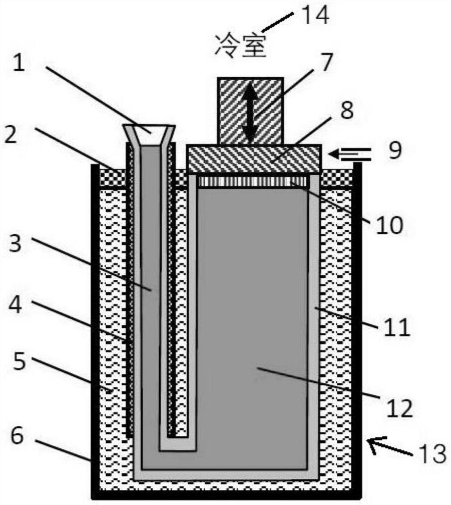
[0026] like figure 1 and figure 2 As shown, the present invention provides a liquid metal heating directional solidification device, comprising a cold chamber 14 and a hot chamber 13, a lifting device 7, a mold shell 11, the mold shell 11 top is an opening, and the opening is provided with The chilling plate 8 is covered, the cold chamber 14 is arranged above the hot chamber 13 , and the lifting device 7 is arranged above the chilling plate 8 . A thermal insulation layer 2 is provided between the hot chamber 13 and the cold chamber 14 , and the formwork 11 is disposed in the thermal chamber 13 through the thermal insulation layer 2 .

[0027] A plurality of nozzles 9 for spraying a cooling medium are arranged in the cold chamber 14, and the nozzles 9 are arranged around the mold shell 11, and the cooling medium is argon. While lifting the mold shell 11, spray argon gas to the mold shell 11 through the nozzle 9 for cooling, so that the heat dissipation efficiency is greatly ...

Embodiment 2

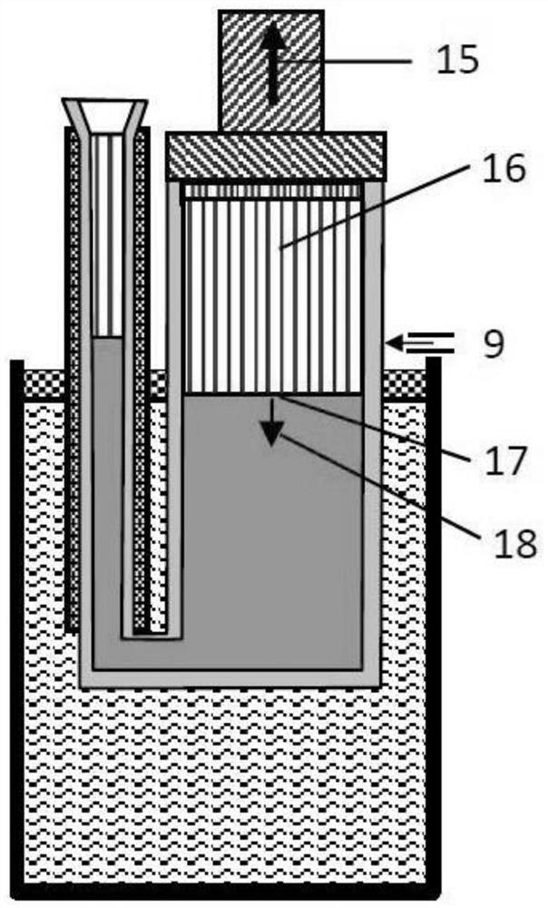
[0035] The present invention also provides a method of directional solidification casting based on the liquid metal heating directional solidification device described in Embodiment 1. Refer to figure 1 and figure 2 , including the steps:

[0036] S1: Fill the crucible 6 in the heat chamber 13 with Al alloy material, heat it through induction or resistance heater until it melts to form liquid metal 5, and replenish Al alloy material so that the upper surface of liquid metal 5 is close to the upper edge of crucible 6 , the distance is 10 to 50mm, forming a liquid metal molten pool, and the temperature is kept at 700°C to 1500°C; a heat insulating layer 2 is set on the liquid metal molten pool, the thickness of the heat insulating layer is 5 to 30mm, and the material of the heat insulating layer 2 can be hollow Ceramic balls, with a diameter of 1 to 5mm, or liquid mold powder.

[0037] S2: Lower the formwork 11 connected to the chilling plate 8 into the liquid metal molten po...


PUM

PropertyMeasurementUnit
thicknessaaaaaaaaaa
diameteraaaaaaaaaa

Abstract

The invention discloses a liquid metal heating directional solidification device which comprises a cold chamber, a hot chamber, a lifting device and a mold shell. An opening is formed in the upper portion of the mold shell, a chilling plate is arranged at the opening, and the cold chamber is arranged above the hot chamber; the hot chamber is a liquid metal molten pool; a heat insulation layer is arranged between the hot chamber and the cold chamber; the mold shell penetrates through the heat insulation layer and is arranged in the hot chamber; a plurality of nozzles for spraying a cooling medium are arranged in the cold chamber, and the nozzles are arranged around the mold shell; and the lifting device is arranged above the chilling plate. While the freckle defect generally existing in the high-temperature alloy directional and single-crystal casting is eliminated, and meanwhile, a conduction and convection mode is used for replacing a radiation mode in a traditional process for heating and cooling, the heat exchange efficiency and the temperature gradient are greatly improved, so that a good condition is created for producing the high-quality directional and single-crystal casting.

Description

technical field [0001] The invention relates to investment casting technology, in particular to a liquid metal heating and directional solidification device and a casting method. Background technique [0002] There are two obvious shortcomings in the existing directional solidification equipment and technology of superalloys. One is that the heating of the mold shell in the heating chamber and the heat dissipation in the cooling chamber are all carried out by radiation, and the efficiency is very low, resulting in a small temperature gradient. Shortcomings such as bulky organization. The second is that the mold shell is pulled downwards, while the casting is directional solidified upwards, which is opposite to the direction of gravity, resulting in the generation of freckle defects. People have used liquid metal cooling in the cold chamber, that is, LMC method (Liquid Metal Kooling,) to replace the radiation to cool the formwork, but the heating method of the formwork in th...

Claims


Application Information

Patent Timeline
Patent Type & Authority Applications(China)
IPC IPC(8): B22D27/04
CPCB22D27/045
Inventor 马德新王富徐维台
Owner 深圳市万泽中南研究院有限公司
Why Eureka
Try Eureka