Directional solidification method capable of eliminating spots in casting
A directional solidification and casting technology, applied in self-solidification methods, chemical instruments and methods, crystal growth, etc., can solve the problems of low temperature gradient and concave solidification interface, achieve high temperature gradient, wide material sources, and eliminate freckles. Effect
- Summary
- Abstract
- Description
- Claims
- Application Information
AI Technical Summary
Problems solved by technology
Method used
Image
Examples
Embodiment 1
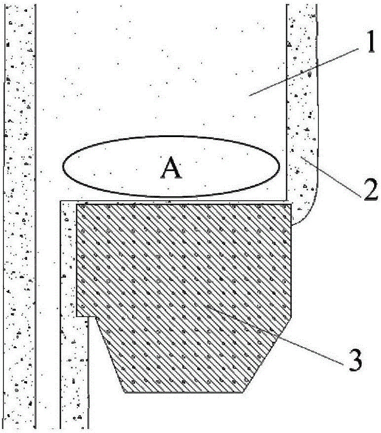
[0037] This embodiment is applied to the directional solidification process of a casting 1 with a sudden change in cross section, such as figure 1 shown. The size of the small section of the casting with sudden change in cross section is 4mm×20mm×100mm, the size of the large section of the casting is 40mm×20mm×25mm, and the material is CMSX-4 superalloy; the specific steps are as follows:
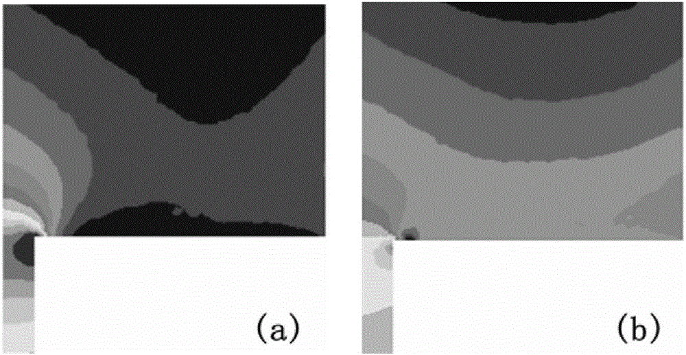
[0038] Step 1, determine the temperature gradient distribution and solidification interface shape during the directional solidification process of the casting. Use ProCAST software to numerically simulate the directional solidification process of casting 1 according to conventional methods, and perform post-processing to obtain figure 1 The temperature gradient distribution and the shape of the solidification interface in the cross-sectional sudden change region shown in A are as follows: figure 2 a with Figure 4 as shown in a.
[0039] Step 2, determine the shape, size and placement...
Embodiment 2
[0052] This embodiment is applied to the directional solidification of a casting 1 with a sudden change in cross section, such as figure 1 shown. The size of the small section of the casting with sudden change in cross section is 4mm×20mm×100mm, the size of the large section of the casting is 40mm×20mm×50mm, and the material is DZ411 superalloy; the specific steps are as follows:
[0053] Step 1, determine the temperature gradient distribution and solidification interface shape during the directional solidification process of the casting. Use ProCAST software to numerically simulate the directional solidification process of casting 1 according to conventional methods, and perform post-processing to obtain figure 1 The temperature gradient distribution and the shape of the solidification interface in the cross-sectional sudden change region shown in A are as follows: image 3 a with Figure 5 as shown in a.
[0054] Step 2, determine the shape, size and placement position...
Embodiment 3
[0067] This embodiment is applied to the directional solidification process of a casting 1 with a sudden change in cross section, such as figure 1 shown. The size of the small section of the casting with sudden change in cross section is 4mm×20mm×100mm, the size of the large section of the casting is 40mm×20mm×25mm, and the material is DZ125 superalloy; the specific steps are as follows:
[0068] Step 1, determine the temperature gradient distribution and solidification interface shape during the directional solidification process of the casting. Use ProCAST software to numerically simulate the directional solidification process of casting 1 according to conventional methods, and perform post-processing to obtain figure 1 The temperature gradient distribution and the shape of the solidification interface in the cross-sectional sudden change region shown in A.
[0069] Step 2, determine the shape, size and placement position of the graphite block. According to the principl...
PUM
| Property | Measurement | Unit |
|---|---|---|
| length | aaaaa | aaaaa |
| length | aaaaa | aaaaa |
| length | aaaaa | aaaaa |
Abstract
Description
Claims
Application Information
 - R&D Engineer
- R&D Manager
- IP Professional
- Industry Leading Data Capabilities
- Powerful AI technology
- Patent DNA Extraction
Browse by: Latest US Patents, China's latest patents, Technical Efficacy Thesaurus, Application Domain, Technology Topic, Popular Technical Reports.
© 2024 PatSnap. All rights reserved.Legal|Privacy policy|Modern Slavery Act Transparency Statement|Sitemap|About US| Contact US: help@patsnap.com


