Micro-fluidic chip photostimulation device, yeast single-cell photoregulation gene expression method and application
A microfluidic chip and yeast cell technology, applied in stress-stimulated microbial growth methods, chemical instruments and methods, and microbial-based methods, can solve problems such as slow effects, high requirements for experimental methods, and time resolution problems
- Summary
- Abstract
- Description
- Claims
- Application Information
AI Technical Summary
Problems solved by technology
Method used
Image
Examples
Embodiment 1
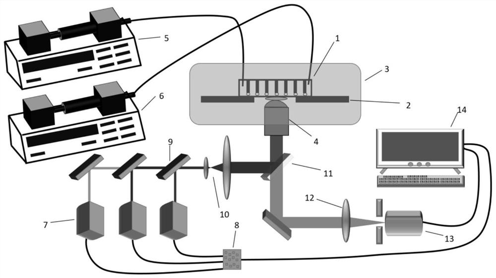
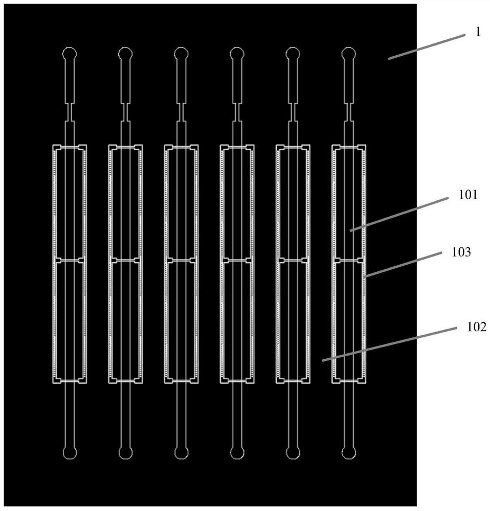
[0072] A microfluidic chip light stimulation device, such as figure 1 As shown, the device includes a cell culture chip 1, a culture control unit and a light stimulation unit for maintaining the growth of living cells. The cell culture chip 1 includes a micro-table array 101 for capturing cells, a glass bottom plate 103 and an intermediate channel 102 for simulating blood vessel circulation. The CAD top view of the cell culture chip 1 is as follows: figure 2As shown, each cell culture chip 1 contains six independent channels. The micro-stage array 101 is made of polydimethylsiloxane, and the gap between it and the glass bottom plate 103 is 4 microns. The cell culture chip 1 is placed on a motorized stage 2 . The culture control unit includes a cage constant temperature incubator 3, which provides a constant temperature environment for the cultivation of yeast cells. The culture control unit also includes a first microinjection pump 5 and a second microinjection pump 6 comm...
Embodiment 2
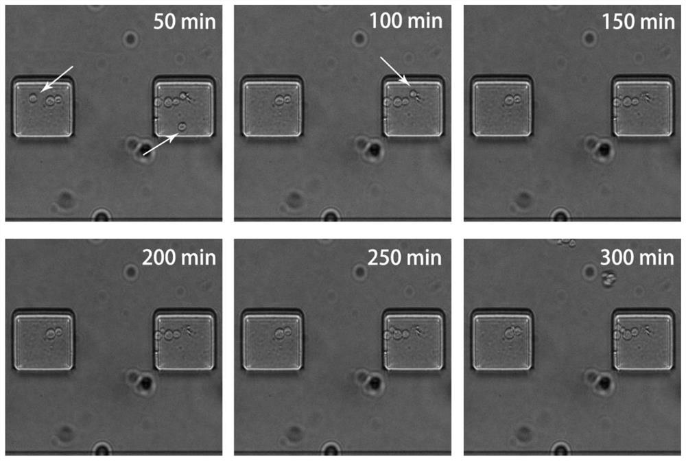
[0074] The cell density of Saccharomyces cerevisiae W303-1a was about 5.5×10 after overnight culture by 600 nm absorbance measurement. 5 cells / ml, inject the yeast cell suspension into the microfluidic cell culture chip at a flow rate of 0.5 ml / min, and observe the cell capture situation through a microscope. Then the yeast extract powder peptone glucose medium was passed through at a flow rate of 0.1 ml / min, and at 30° C., the yeast growth image was imaged under bright-field LED light source as the lighting condition. The result is as image 3 shown. image 3 In the middle, the time in the upper left corner indicates the elapsed time from the introduction of the yeast culture medium, and the white cutting head indicates that the yeast cells with smaller cell diameters, such as newly divided progeny cells, are separated from the micro-stage array 101 of the cell culture chip 1, so no Can cause cell accumulation problems. from image 3 It can be seen that the yeast cells ca...
Embodiment 3
[0076] Using homologous recombination to construct light-stimulus-responsive Saccharomyces cerevisiae cell samples, the schematic diagram is as follows Figure 4 shown. Using PIF3 protein to link the VP16 activation domain constitutes the first module, and NPhyB and the lexA-DBD DNA binding domain constitute the second module. NPhyB undergoes a conformational change under the stimulation of 660nm laser and binds to PIF3 to activate downstream gene expression. However, under the stimulation of far-infrared light at 740 nanometers, NPhyB and PIF3 were dissociated, and the expression of downstream genes was stopped.
[0077] The specific process is as follows:
[0078] (1) Construction of transfection plasmids comprising PIF3-VP16, NPhyB-lexA-DBD and TATAbox-EGFP;
[0079] (2) Configure 1 mol / L lithium acetate to prepare yeast competent cells, and mix the transfection plasmid and competent cells at 42°C for one minute;
[0080] (3) Screen positive clones under appropriate scr...
PUM
 Abstract
Description
Claims
Application Information
 - R&D
- Intellectual Property
- Life Sciences
- Materials
- Tech Scout
- Unparalleled Data Quality
- Higher Quality Content
- 60% Fewer Hallucinations
Browse by: Latest US Patents, China's latest patents, Technical Efficacy Thesaurus, Application Domain, Technology Topic, Popular Technical Reports.
© 2025 PatSnap. All rights reserved.Legal|Privacy policy|Modern Slavery Act Transparency Statement|Sitemap|About US| Contact US: help@patsnap.com


