


Quick Research
Generate reliable direction feasibility study reports for your R&D in just a few steps.

Technical Q&A
Discover and master advanced knowledge NOW. Basics, ideas, possibilities, all at once.

Find Solutions
As an expert in R&D theories, this can generate solutions to your technical problems instantly.

Evaluate Feasibility
Analyze your overall solution with one click, know your potential R&D risks in advance.

Monitor Landscape
Get weekly tech updates, stay abreast of the latest tech innovations and key insights.
Network monitoring system and network monitoring method
A network monitoring and monitoring module technology, applied in transmission systems, digital transmission systems, data exchange networks, etc., can solve problems such as dependence on subjective judgment, network burden, and complex backbone network configuration
- Summary
- Abstract
- Description
- Claims
- Application Information
AI Technical Summary
Problems solved by technology
Method used
Image


Examples
Embodiment 1
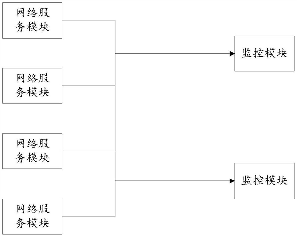
[0028] The embodiment of the present disclosure provides such as figure 1 The network monitoring system shown includes: one or more parallel monitoring modules and multiple network service modules.
[0029] The network service module is configured in the data link layer, and is used to communicate between the network service modules using a pre-configured first communication protocol, generate and transmit log information, and the first communication protocol is between network server modules Routing Protocol.
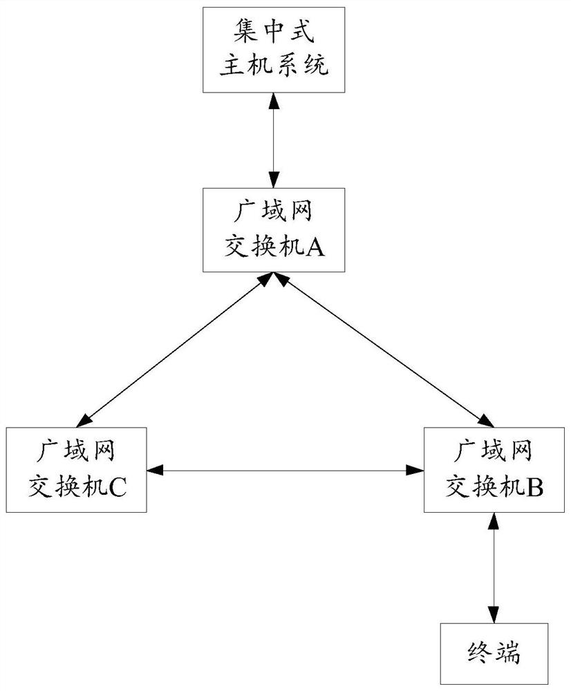
[0030] For example, if figure 2 As shown, the network service module includes the data link layer equipment of the POP point, such as the WAN switch; the WAN switch is a device for expanding the network, which belongs to the data link layer equipment, and is used to realize the communication between the WAN devices; In the application, the WAN switch is connected to the centralized host system (such as a data center), which can provide more connection ports for the ...
Embodiment 2
[0049] Since the embodiment of the present disclosure is further optimized based on the first embodiment, the explanation based on the same system composition and the same name meaning is the same as that of the first embodiment, and will not be repeated here.
[0050] Because the network service module configured in the data link layer can only be applied to a pre-configured User Datagram Protocol (English full name User Datagram Protocol, UDP protocol for short) transmission log information. For example, if Figure 5 As shown, the WAN switch can only use its configured system log protocol (or system record protocol, Syslog protocol for short) to transmit the log information to the destination, for example, the destination is the Rsyslog server of the remote log server. The Syslog protocol is a connectionless protocol based on the UDP protocol, which provides a method for sending encapsulated IP data packets without establishing a connection, that is, there is no security mec...
Embodiment 3
[0067] Since the embodiment of the present disclosure is further optimized based on the first embodiment and / or the second embodiment, the explanation based on the same system composition and the same name meaning is the same as that of the above embodiment, and will not be repeated here.
[0068] Since multiple parallel monitoring modules in Embodiment 1 and / or Embodiment 2 cannot completely solve the problem of centralized transmission of log information to one of the monitoring modules, that is, the problem of single-point transmission. It may still cause a bottleneck problem in processing log information. optional, such as Figure 4 As shown, the system also includes a load balancing module. The load balancing module is arranged in front of the monitoring module, and is used for distributing the received log information to the monitoring module based on a preset load balancing strategy.
[0069] The load balancing strategy is to distribute the log information to multiple...
PUM
 Abstract
Description
Claims
Application Information
 - R&D Engineer
- R&D Manager
- IP Professional
- Industry Leading Data Capabilities
- Powerful AI technology
- Patent DNA Extraction
Browse by: Latest US Patents, China's latest patents, Technical Efficacy Thesaurus, Application Domain, Technology Topic, Popular Technical Reports.
© 2024 PatSnap. All rights reserved.Legal|Privacy policy|Modern Slavery Act Transparency Statement|Sitemap|About US| Contact US: help@patsnap.com