
Low-power-consumption external interrupt wake-up circuit and control method thereof

An external interrupt and wake-up circuit technology, applied in the direction of reducing power consumption, logic circuit, logic circuit connection/interface layout, etc., can solve the problem of increasing the scale of digital codes and digital logic complexity, and cannot use traditional processing methods. Edge detection, increase Constant power supply digital logic power consumption and other issues, to achieve the effect of small quantity, small occupied layout area, and few types of devices

Active Publication Date: 2021-01-26
合肥寰芯微电子科技有限公司
View PDF9 Cites 2 Cited by
  • Summary
  • Abstract
  • Description
  • Claims
  • Application Information

AI Technical Summary

Problems solved by technology

In the deep sleep state, the digital logic reset part is in a state of no power supply and no clock, and the traditional processing method cannot be used for edge detection. It belongs to the wake-up reset of the power-on process rather than a simple soft reset process. The processing method is difficult to implement.
[0006] In the prior art, clock-independent digital combinatorial logic is often used to wake up the circuit, but it will multiply the size of the digital code and the complexity of the digital logic, and will significantly increase the power consumption of the digital logic with constant power supply

Method used


Image

  • Low-power-consumption external interrupt wake-up circuit and control method thereof
  • Low-power-consumption external interrupt wake-up circuit and control method thereof
  • Low-power-consumption external interrupt wake-up circuit and control method thereof

Examples


Embodiment Construction

[0039] A preferred embodiment of the present invention will be described in detail below with reference to the accompanying drawings.

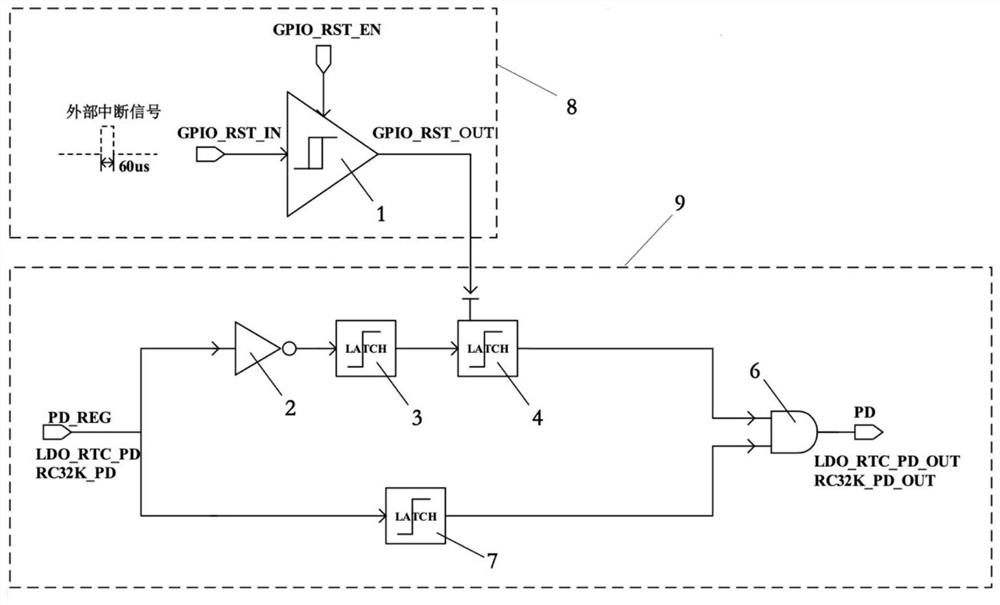
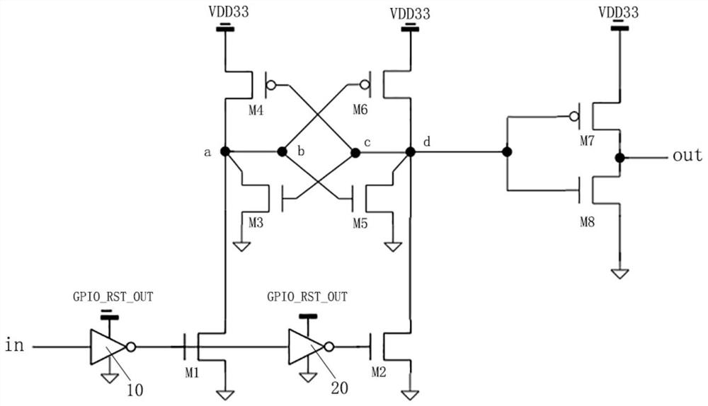
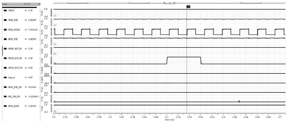
[0040] The present invention aims to propose such a low-power external interrupt wake-up circuit. Since the circuit works in a deep sleep state, there is no clock and no power supply. It is necessary to break through the idea of ​​digital dominant participation in edge detection in the traditional reset circuit and introduce a new wake-up method. The circuit principle does not require the leading participation of digital logic, and the external interrupt excitation forces the analog circuit part to forcibly turn on the power supply and clock, thereby resetting the entire chip circuit. Compared with the button reset signal, the external interrupt signal lasts for a shorter high level time, generally only a few clock cycles, which means that the wake-up circuit must be able to accept the extremely short duration of the external interrupt pulse, a...


PUM


Abstract

The invention discloses a low-power-consumption external interrupt wake-up circuit. The circuit comprises a Schmitt trigger, a first phase inverter, a first level converter, a second level converter,a third level converter and an AND gate, wherein the Schmitt trigger comprises an input interface used for receiving an external interrupt signal, a signal control end used for controlling the enabling of the external interrupt signal, and an output interface; an input end of the first phase inverter is connected with a power supply control signal for controlling a clock module power supply, and an output end of the first phase inverter is connected with the input end of the first level converter; an output end of the first level converter is connected with an input end of the second level converter; the second level converter comprises two-stage power supply, a first-stage power supply end of the second level converter is connected with the output interface of the Schmitt trigger, and anoutput end of the second level converter is connected with one input end of the AND gate; an input end of the third level converter is connected with a power supply control signal, and an output end of the third level converter is connected with the other input end of the AND gate; and the AND gate outputs a bottom circuit power supply signal for controlling power supply of the bottom circuit.

Description

technical field [0001] The invention relates to the field of circuit wake-up, in particular to a low-power consumption external interrupt wake-up circuit and a control method thereof. Background technique [0002] With the rise of the Internet of Everything and artificial intelligence, more and more low-cost, low-power wireless communication solutions are emerging to provide solutions to the "last mile" problem of the Internet of Things. Low-power design has become a major The technical focus of chip manufacturers. [0003] In order to achieve extremely low power consumption, the chip often needs to enter a deep sleep state with no clock, no power supply or a small part of power supply when there is no work task. This "suicide" power-off that cuts off its own power supply poses a challenge to the design of the wake-up circuit. Therefore, whether the wake-up circuit can operate normally is the key core of the low-power application of the entire chip. [0004] In low-power a...

Claims


Application Information

Patent Timeline
Patent Type & Authority Applications(China)
IPC IPC(8): H03K19/0185H03K19/017
CPCH03K19/017H03K19/0013H03K19/0185Y02D10/00
Inventor 游超于涛张杰
Owner 合肥寰芯微电子科技有限公司
Learn More